
SLIDE 1
11/13/2019 1
LS Wong and Associates
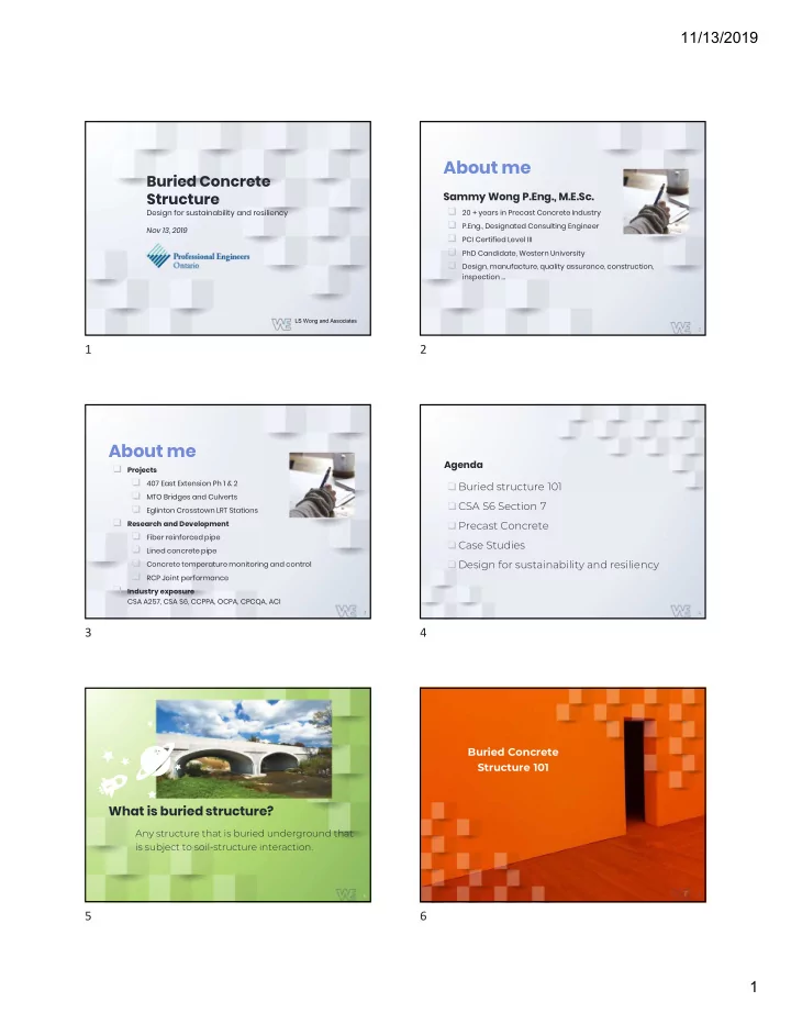
Buried Concrete Structure
Design for sustainability and resiliency Nov 13, 2019
2
About me
Sammy Wong P.Eng., M.E.Sc. ❑ 20 + years in Precast Concrete Industry ❑ P.Eng., Designated Consulting Engineer ❑ PCI Certified Level III ❑ PhD Candidate, Western University ❑ Design, manufacture, quality assurance, construction,
inspection …
3
About me
❑ Projects ❏ 407 East Extension Ph 1 & 2 ❏ MTO Bridges and Culverts ❏ Eglinton Crosstown LRT Stations ❑ Research and Development ❏ Fiber reinforced pipe ❏ Lined concrete pipe ❏ Concrete temperature monitoring and control ❏ RCP Joint performance ❑ Industry exposure
CSA A257, CSA S6, CCPPA, OCPA, CPCQA, ACI
Agenda
❑ Buried structure 101 ❑ CSA S6 Section 7 ❑ Precast Concrete ❑ Case Studies ❑ Design for sustainability and resiliency
4 5
What is buried structure?
Any structure that is buried underground that is subject to soil-structure interaction.
Buried Concrete Structure 101
6