
SLIDE 1
A Study on Hydrogen Explosion Possibility in the Containment Filtered Venting System During Severe Accident
Gi Hyeon Choia, Ji-Hwan Hwanga, Tae Woon Kimb,c and Dong-Wook Jernga*
aChung-Ang University, 84 Heukseok-ro, Dongjak-gu, Seoul, Republic Korea bKorea Atomic Energy Research Institute, 111 Daedeok-daero 989 beon-gil, Yuseong-gu, Daejeon, Republic Korea cNuclear Engineering Services and Solutions, 756-27, Daedeok-daero, Yuseong-gu, Daejeon, Republic Korea *Corresponding author: dwjerng@cau.ac.kr
- 1. Introduction
Since the Fukushima accident, the passive safety systems are introduced to cope with Station Black Out (SBO). Among them, the Containment Filtered Venting System (CFVS) filters radioactive materials then vent the gases to the external environment, maintain the pressure
- f the containment building [1]. The wet-type CFVS
consists of inlet and outlet pipes and a vessel. An isolation valve is installed in front of the inlet pipe, to prevent gas leakage in normal operation. A scrubber and scrubbing pool, which decontaminate radioactive materials, is located at the CFVS vessel. A metal fiber filter, which is at the upper side of the CFVS vessel, filters the droplets and aerosols which are not filtered at the scrubbing pool. When the CFVS operates, the atmosphere of the containment building, which consists
- f flammable gas such as hydrogen and carbon monoxide
generated by fuel oxidation and Molten Corium- Concrete Interaction (MCCI), flows into the CFVS vessel. When the gases pass through the scrubbing pool, the steam condenses and the fraction of flammable gases may increase. In such a situation, resulting in the accumulation of flammable gas inside the CFVS the flammable gas may detonate, threatening the integrity of the CFVS. Therefore, it is essential to estimate the hydrogen risk in the CFVS vessel during CFVS
- peration.
- 2. Method of analyses
In this study, MELCOR 1.8.6 was used. The Korean 1000MWe pressurized water reactor, the Optimized Power Reactor 1000 (OPR1000), was used as a reference nuclear power plant. 2.1 Nodalization The OPR1000 was modeled as two hot-legs, two steam generators, four cold-legs, four Safety Injection Tanks (SITs), a pressurizer, and a reactor. The core initial heat output was set to 2815 MWt. The initial inventory
- f coolant in the RCS was 210 tons and 50 tons for each
- SIT. The major parameters of the OPR1000 are listed in
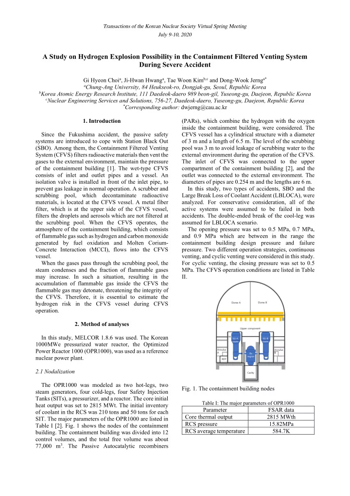
Table I [2]. Fig. 1 shows the nodes of the containment
- building. The containment building was divided into 12
control volumes, and the total free volume was about 77,000 m3. The Passive Autocatalytic recombiners (PARs), which combine the hydrogen with the oxygen inside the containment building, were considered. The CFVS vessel has a cylindrical structure with a diameter
- f 3 m and a length of 6.5 m. The level of the scrubbing
pool was 3 m to avoid leakage of scrubbing water to the external environment during the operation of the CFVS. The inlet of CFVS was connected to the upper compartment of the containment building [2], and the
- utlet was connected to the external environment. The
diameters of pipes are 0.254 m and the lengths are 6 m. In this study, two types of accidents, SBO and the Large Break Loss of Coolant Accident (LBLOCA), were
- analyzed. For conservative consideration, all of the
active systems were assumed to be failed in both
- accidents. The double-ended break of the cool-leg was
assumed for LBLOCA scenario. The opening pressure was set to 0.5 MPa, 0.7 MPa, and 0.9 MPa which are between in the range the containment building design pressure and failure
- pressure. Two different operation strategies, continuous
venting, and cyclic venting were considered in this study. For cyclic venting, the closing pressure was set to 0.5
- MPa. The CFVS operation conditions are listed in Table
II.
- Fig. 1. The containment building nodes