A LEVEL SET MODEL FOR DELAMINATION ANALYSIS WITH LARGE ELEMENTS F.P. - - PDF document

a level set model for delamination analysis with large
SMART_READER_LITE
LIVE PREVIEW

A LEVEL SET MODEL FOR DELAMINATION ANALYSIS WITH LARGE ELEMENTS F.P. - - PDF document

18 TH INTERNATIONAL CONFERENCE ON COMPOSITE MATERIALS A LEVEL SET MODEL FOR DELAMINATION ANALYSIS WITH LARGE ELEMENTS F.P. van der Meer 1,2 *, N. Mo s 2 , L.J. Sluys 1 1 Faculty of Civil Engineering and Geosciences, Delft University of


slide-1
SLIDE 1

18TH INTERNATIONAL CONFERENCE ON COMPOSITE MATERIALS

1 Introduction In this paper, a new approach to the computational modeling of delamination is presented. Currently, delamination is most often modeled by means of interface elements, also referred to as decohesion

  • elements. In that approach, a cohesive traction is

applied on the crack surface to represent the nonlinear material behavior around the crack tip. The crack front is modeled as a narrow band in which the traction is decreasing, the cohesive zone. Crack initiation and propagation can be dealt with naturally through the relation between crack opening and traction. However, cohesive modeling has a serious limitation, which is that it requires elements to be several times smaller than the cohesive zone length. When elements are too large, spurious oscillations

  • ccur in the response, which endanger the stability
  • f the solution procedure and harm the accuracy of

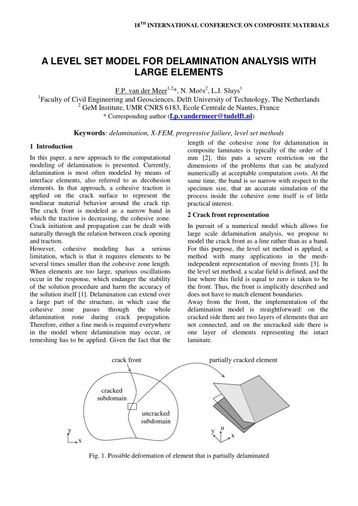
the solution itself [1]. Delamination can extend over a large part of the structure, in which case the cohesive zone passes through the whole delamination zone during crack propagation. Therefore, either a fine mesh is required everywhere in the model where delamination may occur, or remeshing has to be applied. Given the fact that the length of the cohesive zone for delamination in composite laminates is typically of the order of 1 mm [2], this puts a severe restriction on the dimensions of the problems that can be analyzed numerically at acceptable computation costs. At the same time, the band is so narrow with respect to the specimen size, that an accurate simulation of the process inside the cohesive zone itself is of little practical interest. 2 Crack front representation In pursuit of a numerical model which allows for large scale delamination analysis, we propose to model the crack front as a line rather than as a band. For this purpose, the level set method is applied, a method with many applications in the mesh- independent representation of moving fronts [3]. In the level set method, a scalar field is defined, and the line where this field is equal to zero is taken to be the front. Thus, the front is implicitly described and does not have to match element boundaries. Away from the front, the implementation of the delamination model is straightforward: on the cracked side there are two layers of elements that are not connected, and on the uncracked side there is

  • ne layer of elements representing the intact

laminate.

A LEVEL SET MODEL FOR DELAMINATION ANALYSIS WITH LARGE ELEMENTS

F.P. van der Meer1,2*, N. Moës2, L.J. Sluys1

1Faculty of Civil Engineering and Geosciences, Delft University of Technology, The Netherlands 2 GeM Institute, UMR CNRS 6183, Ecole Centrale de Nantes, France

* Corresponding author (f.p.vandermeer@tudelft.nl)

Keywords: delamination, X-FEM, progressive failure, level set methods

  • Fig. 1. Possible deformation of element that is partially delaminated
slide-2
SLIDE 2

Near the front, however, a special kinematic formulation is required. Three displacement fields are distinguished: one on the uncracked side, and two on the cracked side (see Fig. 1). The two fields

  • n the cracked side are both connected to the field
  • n the uncracked side with a weak discontinuity.

This weak discontinuity is accomplished with a mesh-independent method for strong discontinuities in combination with Lagrange multipliers [4] or Nitsche's method [5] to annihilate the displacement

  • jump. For the strong discontinuities, Hansbo and

Hansbo's method [6] is applied, which is another way to implement the Heaviside enrichment introduced by Moës et al. [7]. 3 Crack growth Along the crack front, the energy release for crack growth is computed with the jump in Eshelby tensor

  • ver the crack front. This is used in combination

with an explicit crack growth law to relate the front velocity to the stress and strain field. The velocity is extended through the domain with a fast marching method after which the level set field is updated, which gives the new crack front location. For analysis of progressive delamination, a staggered solution algorithm is proposed. In each time step, first the linear mechanics problem is solved for a fixed delamination crack, and then the crack front location is updated based on the computed displacement field, for which a second system of equations is solved on the partial domain that contains the crack front. For initiation, the same fracture mechanics criterion based on the Eshelby tensor is used. Even in absence

  • f a crack front, a virtual jump in Eshelby stress

tensor can be computed assuming free edge boundary conditions for the individual ply. This is not intended as a reliable indicator for the stage at which first damage occurs in the structure, but it does allow for a fully automated transition from the uncracked state to the state with a large growing crack in which the energy approach is valid. 4 Numerical example: edge-cracked torsion In a first numerical example, we demonstrate the efficiency of the energy release rate computation with the jump in Eshelby tensor. The energy release rate is computed for the 6 point edge-cracked torsion (6ECT) test by Pereira et al. [8] with a fixed straight crack front. For this case, we let the crack front coincide with an element boundary, to end up with a simple and efficient method to compute the energy

  • release. In Fig. 2, the computed energy release is

compared with the values reported by Pereira et al. [8]. The mesh is also shown and it can be observed to be relatively coarse, with neither through-the- thickness discretization nor in-plane refinement near the crack front (in contrast with the virtual crack closure technique (VCCT) analysis by Pereira et al. [8]). Partitioning into pure mode rates GII and GIII was possible because both cracked sublaminates are

  • f equal thickness and symmetric. In the generic

case, the theoretic definition of the modes becomes more elusive, and mode partitioning more challenging.

  • Fig. 2. Computed energy release rates and

deformation from the 6ECT test These results indicate that using the jump in Eshelby tensor for energy release computations may also be

  • f use in cases where one is not interested in

analyzing progressive failure and the VCCT would

  • therwise be used.
slide-3
SLIDE 3

3

5 Numerical example: cracked shear lap In a second numerical example, we include crack growth and the level set method in a cracked shear lap (CSL) test. The analysis is performed in 2D, in which case the crack front propagates at a constant load level. For reference, the case is also simulated with cohesive elements. In Fig. 3, load displacement curves from the two analyses are shown. The equivalence of the results from the two analyses is

  • bvious. The gain in efficiency can also be observed

when the magnitude of the displacement increments is compared. In the cohesive analysis, time steps have to be small to find convergence – the crack front can only move a very small distance in each time step. Whereas in the current method, bigger time steps are possible with the same accuracy. A further comparison is made in Fig. 4, where the crack front location from the two analyses is shown for the same prescribed displacement level. It can be

  • bserved that the level set front, which is superposed
  • nto the cohesive zone results is of the same shape

and location as the cohesive zone. Furthermore, a much coarser mesh could be used with the level set

  • method. The mesh shown in Fig. 4 was the coarsest

possible mesh to obtain convergence in the cohesive zone analysis, even though a robust arc-length method was used. Larger elements could be used in the level set analysis (see Fig. 5 where the deformation from the level set analysis for a single time step is shown). We note that the relative advantage could be further increased by scaling the specimen size. With the cohesive zone, the absolute element size should remain the same, while with the level set method the elements can scale along with the specimen.

  • Fig. 4. Comparison between cohesive damage and

level set crack front for equal displacement level in CSL test

  • Fig. 3. Load-displacement relation for CSL test: level set analysis versus conventional cohesive method
  • Fig. 5. Deformation in level set analysis of CSL test
slide-4
SLIDE 4

6 Discussion With this new approach, it is shown that, within the context of shell theory, crack growth can be modeled without representation of a cohesive zone or stress

  • singularities. The resulting model does not have the

restrictive mesh requirements that exist for cohesive methods (multiple elements over the cohesive zone)

  • r stress intensity methods (multiple elements

through the thickness of the laminate). Rather, the energy release rate is computed along the front from the jump in Eshelby tensor, which is related to regular deformation quantities. On top of the increase in element size, load increments or time steps can be larger than with cohesive elements, because the indirect nature of crack growth in cohesive models via local increase

  • f a damage variable is eliminated. Therefore this

approach allows for the efficient simulation of large scale progressive delamination. References

 P.W. Harper and S.R. Hallett “Cohesive zone length in numerical simulations of composite delamination”. Engineering Fracture Mechanics, Vol. 75, pp 4774- 4792, 2008  Q.D. Yang and B.N. Cox “Cohesive models for damage evolution in laminated composites”. International Journal of Fracture, Vol. 133, pp 107- 137, 2005.  J.A. Sethian “Level Set Methods and Fast Marching Methods”. Cambridge University Press, 1999.  É. Béchet, N. Moës and B. Wohlmuth “A stable Lagrange multiplier space for stiff interface conditions within the extended finite element method”. International Journal for Numerical Methods in Engineering, Vol. 78, pp 931-954, 2008.  J. Mergheim and P. Steinmann “A geometrically nonlinear FE approach for the simulation of strong and weak discontinuities”. Computer Methods in Applied Mechanics and Engineering, Vol. 195, pp 5037-5052, 2006.  A. Hansbo and P. Hansbo “A finite element method for the simulation of strong and weak discontinuities in solid mechanics”. Computer Methods in Applied Mechanics and Engineering, Vol. 193, pp 3523- 3540, 2004.  N. Moës, J. Dolbow and T. Belytschko “A finite element method for crack growth without remeshing”. International Journal for Numerical Methods in Engineering, Vol. 46, pp 131-150, 1999.  A.B. Pereira, A.B. de Morais and M.F.S.F. de Moura “Design and analysis of a new six-point edge crack torsion (6ECT) specimen for mode III interlaminate fracture characterization.” Composites Part A, Vol. 42, pp 131-139, 2011.