8150 Variable-Height Keyboard Slide KV 8150 Major Dimensions and - - PDF document

8150 variable height keyboard slide
SMART_READER_LITE
LIVE PREVIEW

8150 Variable-Height Keyboard Slide KV 8150 Major Dimensions and - - PDF document

8150 Variable-Height Keyboard Slide KV 8150 Major Dimensions and Mounting Hole Locations Slide 12 * 13 14 * 15 16 * 17 18 * 19 20 * 21 22 * 23 24 * 25 26 * 27 28 * 29 30 * Size Side Travel A B C D E F G Specifications 7


slide-1
SLIDE 1

8150 Variable-Height Keyboard Slide

Specifications

  • 7 position, adjustable and reversible mounting bracket.
  • Friction latch securely holds keyboard in extended position.
  • Metal Ball Bearing Retainer and three precision steel ball bearings per inch of race for

smooth quiet movement and durability.

  • Drawer track member disconnects quickly using positive lever release for easier installation.
  • Anti-rebounding, Stay-Close feature holds tray in closed position.
  • Bright electro-zinc plated with lacquered finish for better corrosion resistance. Black finish available.

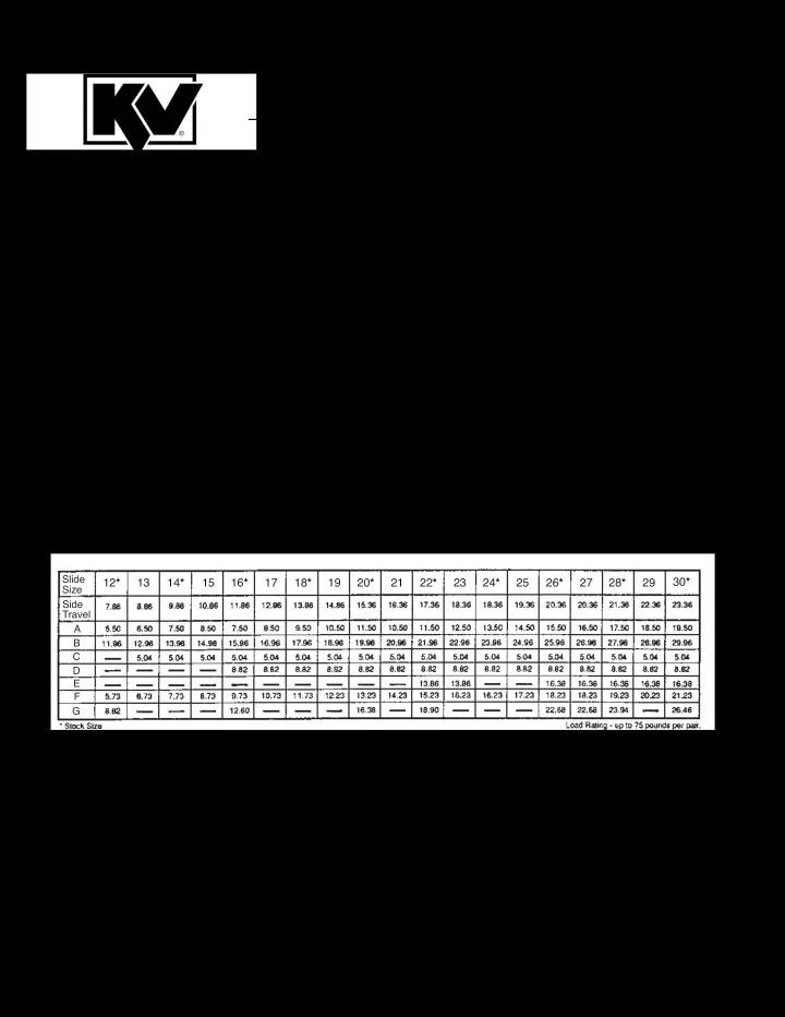
PATENTS PENDING KV 8150 Major Dimensions and Mounting Hole Locations

Slide Size Side Travel A B C D E F G

12* 13 14* 15 16* 17 18* 19 20* 21 22* 23 24* 25 26* 27 28* 29 30*

slide-2
SLIDE 2

For Best Results, Read Instructions First! These instructions show how to install the KV 8150 Keyboard Slide. Please note that improper installation may void the Knape & Vogt Lifetime Limited Warranty. To install the slides correctly, follow these instructions, use only KV hardware, and make no modifications. If you have questions

  • r need additional information, please contact the

factory. Application

  • Recommended for keyboards.
  • Mounting brackets adjust from 2-11/32" to

3-11/16" in 7/32" increments.

  • Maximum keyboard tray width not exceeding 24

inches.

  • Cabinet members must be mounted parallel

to each other and perpendicular to the work surface front.

  • Use #8 x 5/8" Pan Head screws to mount

slide to surface and tray. Use #8 x 1/4" thread cutting screws to secure adjustable brackets at desired height.

  • Consult factory for advice on unusual

applications. Installation Step 1 Identification. Unpack the slides and identify the left hand and right hand slides. The mounting plates are welded to the

  • utside of the (larger) cabinet members. The

keyboard tray will fit flush against the side of the (smaller) drawer members. See figure 1. The right angle mounting brackets are packaged with left and right hand slides unattached. Figure 1. Figure 2. Figure 3.

Installation Instructions for:

8150 Variable-Height Keyboard Slide

slide-3
SLIDE 3

Step 2 Separate parts. Press the lever and pull to separate the cabinet and drawer members as shown in Figure 2. Step 3 Adjust brackets. Set the adjustable brackets to the desired height as shown in figure 3. The brackets may face either inwards or outwards. See diagram on back page for height dimension. Step 4 Install cabinet members. Mount the cabinet members to the underside of the case as shown in figure 4. Refer to drawing on back cover for mounting hole dimensions. Hole location varies dependent on whether the brackets face inwards or outwards. Fasten screws only through the front slotted holes. Additional screws must be added through the other holes after final adjustment. NOTE: The center slotted holes are for front-to-back

  • adjustment. The other slotted holes are for side-to-

side adjustment. Step 5 Install drawer members. Mount the drawer members to the side of the keyboard tray as shown in figure 5. Refer to drawing

  • n front cover for mounting hole dimensions. Fasten

screws only through the slotted holes. Additional screws must be added through the round holes after final adjustment. Step 6 Assembly. First, check that the ball retainers are held in the forward position. Insert the drawer members into the cabinet members as shown in figure 6. Close the drawer completely. The force to close the drawer may be more than normal the last few inches, as the ball bearings must slip into the correct syn- chronous position. Step 7 Check and adjust installation. Open the drawer and check for proper operation. Make adjustments as needed. Then install additional screws in the round holes. Securely tighten all screws. Figure 4. Figure 5. Figure 6.

Mount drawer members through slots to sides of keyboard tray with #8 x 5/8

  • screws. (do not tighten)

Drawer members are unhanded. Install Drawer Members Figure 5.

slide-4
SLIDE 4

Limited Lifetime Warranty Knape & Vogt Manufacturing Company guarantees its drawer slides and builder’s hardware products against failure or defects for so long as the purchaser

  • r end user owns them. This warranty is void if any

damage to the product is due to misuse, abuse, neglect, accident, improper installation or any uses contrary to the instructions accompanying the prod-

  • uct. This warranty covers the cost of the defective

part and not the cost of removal, installation or other incidental charges. The foregoing are the purchaser’s exclusive remedies. Knape & Vogt Manufacturing Company assumes no liability for special or conse- quential damages. Replacement product may be obtained by returning the product, transportation charges prepaid, together with a receipt of purchase or other documents acknowledging the sale of the product, addressed to the Knape & Vogt Manufacturing Company, Attention: Customer Services Department. The warranty set forth above is in lieu of any other warranties, express or implied, including warranties

  • r merchantability and fitness for use.

Major Dimensions, Mounting Hole Locations and Adjustable Bracket Settings.