
SLIDE 1
4/25/2016 1
Understanding Gas Hydrates and its Utility for Energy Solutions
Rajnish Kumar
4/25/2016 1
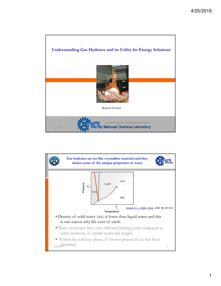
Gas hydrates are ice like crystalline material and they shares some of the unique properties of water
- Density of solid water (ice) is lower than liquid water and this
Cooper, A.I., J. Mater. Chem., 2000, 10, 207-234
y ( ) q is one reason why life exist of earth.
- Water molecules have very different boiling point compared to
- ther molecule of similar molecular weight.
- Within the solid ice phase, 13 known phases of ice has been
identified
4/25/2016 2