3D Viewing: the Synthetic Camera Programmers reference model for - - PDF document

3d viewing the synthetic camera
SMART_READER_LITE
LIVE PREVIEW

3D Viewing: the Synthetic Camera Programmers reference model for - - PDF document

I N T R O D U C T I O N T O C O M P U T E R G R A P H I C S I N T R O D U C T I O N T O C O M P U T E R G R A P H I C S 3D Viewing: the Synthetic Camera Programmers reference model for specifying 3D view


slide-1
SLIDE 1

1

I N T R O D U C T I O N T O C O M P U T E R G R A P H I C S

Andries van Dam September 20, 2005 3D Viewing II

3D Viewing II

I N T R O D U C T I O N T O C O M P U T E R G R A P H I C S

Andries van Dam September 20, 2005 3D Viewing II 1/22

  • Programmer’s reference model for specifying 3D

view projection parameters to the computer

  • General synthetic camera: each package has its own

but they are all (nearly) equivalent. Many ways to specify camera parameters, e.g., view direction. PHIGS† Camera, Computer Graphics: Principles and Practice, ch. 6 and 7)

– position of camera –

  • rientation

– field of view (wide angle, normal…) – depth of field (near distance, far distance) – focal distance – tilt of view/film plane (if not normal to view direction, produces oblique projections) – perspective or parallel projection? (camera near objects

  • r an infinite distance away)
  • CS123 uses a simpler, slightly less powerful model

than the book’s

  • mit tilt of view/film plane, focal distance (blurring)

3D Viewing: the Synthetic Camera

† This package is no longer in use but still has the most general synthetic camera model for perspective and parallel projections.

I N T R O D U C T I O N T O C O M P U T E R G R A P H I C S

Andries van Dam September 20, 2005 3D Viewing II 2/22

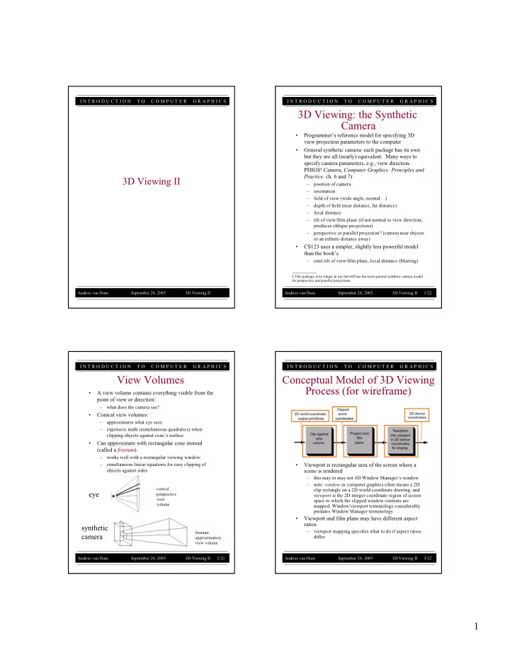
  • A view volume contains everything visible from the

point of view or direction:

– what does the camera see?

  • Conical view volumes:

– approximates what eye sees – expensive math (simultaneous quadratics) when clipping objects against cone’s surface

  • Can approximate with rectangular cone instead

(called a frustum)

– works well with a rectangular viewing window – simultaneous linear equations for easy clipping of

  • bjects against sides

View Volumes

conical perspective view volume

eye

frustum approximation, view volume

synthetic camera

I N T R O D U C T I O N T O C O M P U T E R G R A P H I C S

Andries van Dam September 20, 2005 3D Viewing II 3/22

  • Viewport is rectangular area of the screen where a

scene is rendered

– this may or may not fill Window Manager’s window – note: window in computer graphics often means a 2D clip rectangle on a 2D world coordinate drawing, and viewport is the 2D integer coordinate region of screen space to which the clipped window contents are

  • mapped. Window/viewport terminology considerably

predates Window Manager terminology

  • Viewport and film plane may have different aspect

ratios

– viewport mapping specifies what to do if aspect ratios differ

Conceptual Model of 3D Viewing Process (for wireframe)

slide-2
SLIDE 2

2

I N T R O D U C T I O N T O C O M P U T E R G R A P H I C S

Andries van Dam September 20, 2005 3D Viewing II 4/22

  • We need to know six things about our synthetic

camera model in order to take a picture

  • Position of the camera (from where it’s looking)
  • The Look vector specifies in what direction the

camera is pointing

  • The camera’s Orientation is determined by the Look

vector and the angle through which the camera is rotated about that vector, i.e., the direction of the Up vector

View Volume (1/2)

Position Up vector Look vector Front clipping plane Back clipping plane Width angle Height angle

I N T R O D U C T I O N T O C O M P U T E R G R A P H I C S

Andries van Dam September 20, 2005 3D Viewing II 5/22

  • Aspect ratio of the electronic “film:” ratio of width to

height

  • Height angle: determines how much of the scene we

will fit into our view volume; larger height angles fit more of the scene into the view volume (width angle determined by height angle and aspect ratio)

– the greater the angle, the greater the amount of perspective distortion

  • Front and back clipping planes: limit extent of

camera’s view by rendering (parts of) objects lying between them and throwing away everything outside

  • f them
  • Optional parameter — Focal length: often used for

photorealistic rendering; objects at distance Focal length from camera rendered in sharp detail, objects closer or farther away get blurred; reduction in visibility is continuous

– your camera won’t be implementing focal length blurring

View Volume (2/2)

I N T R O D U C T I O N T O C O M P U T E R G R A P H I C S

Andries van Dam September 20, 2005 3D Viewing II 6/22

  • Determining the Position is analogous to a

photographer deciding the vantage point from which to shoot a photo

  • Three degrees of freedom: x, y, and z coordinates in

3-space

  • This x, y, z coordinate system is right-handed: if you
  • pen your right hand, align your palm and fingers

with the +x axis, and curl your fingers towards the +y axis, your thumb will point along the +z axis

Position

I N T R O D U C T I O N T O C O M P U T E R G R A P H I C S

Andries van Dam September 20, 2005 3D Viewing II 7/22

  • Orientation is specified by a point in 3D space

to look at (or a direction to look in) and an angle

  • f rotation about this direction
  • Default (canonical) orientation is looking down

the negative z-axis and up direction pointing straight up the y-axis

  • In general the camera is located at the origin and

is looking at an arbitrary point with an arbitrary up direction

  • This is a little abstract…easier formulation?

Orientation

Up vector Look vector point to look at (x’, y’, z’) camera Position

  • z

z y x

slide-3
SLIDE 3

3

I N T R O D U C T I O N T O C O M P U T E R G R A P H I C S

Andries van Dam September 20, 2005 3D Viewing II 8/22

  • More concrete way to say the same thing as orientation

– soon you’ll learn how to express orientation in terms of Look and Up vectors

  • Look Vector

– the direction the camera is pointing – three degrees of freedom; can be any vector in 3-space

  • Up Vector

– determines how the camera is rotated around the Look vector – for example, whether you’re holding the camera horizontally or vertically (or in between) – projection of Up vector must be in the plane perpendicular to the look vector (this allows Up vector to be specified at an arbitrary angle to its Look vector)

Look and Up Vectors

Up vector Look vector Position Projection of up vector

I N T R O D U C T I O N T O C O M P U T E R G R A P H I C S

Andries van Dam September 20, 2005 3D Viewing II 9/22

  • Analogous to the size of film used in a camera
  • Determines proportion of width to height of image

displayed on screen

  • Square viewing window has aspect ratio of 1:1
  • Movie theater “letterbox” format has aspect ratio of

2:1

  • NTSC television has an aspect ratio of 4:3, and

HDTV is 16:9

Aspect Ratio

1:1 2:1 16:9 I N T R O D U C T I O N T O C O M P U T E R G R A P H I C S

Andries van Dam September 20, 2005 3D Viewing II 10/22

  • Determines amount of perspective distortion in

picture, from none (parallel projection) to a lot (wide- angle lens)

  • In a frustum, two viewing angles: width and height

angles

  • Choosing View angle analogous to photographer

choosing a specific type of lens (e.g., a wide-angle or telephoto lens)

View Angle (1/2)

Width angle Height angle

I N T R O D U C T I O N T O C O M P U T E R G R A P H I C S

Andries van Dam September 20, 2005 3D Viewing II 11/22

  • Lenses made for distance shots often have a nearly

parallel viewing angle and cause little perspective distortion, though they foreshorten depth

  • Wide-angle lenses cause a lot of perspective

distortion

View Angle (2/2)

Resulting picture

slide-4
SLIDE 4

4

I N T R O D U C T I O N T O C O M P U T E R G R A P H I C S

Andries van Dam September 20, 2005 3D Viewing II 12/22

  • Volume of space between Front and Back clipping

planes defines what camera can see

  • Position of planes defined by distance along Look

vector

  • Objects appearing outside of view volume don’t get

drawn

  • Objects intersecting view volume get clipped

Front and Back Clipping Planes (1/4)

I N T R O D U C T I O N T O C O M P U T E R G R A P H I C S

Andries van Dam September 20, 2005 3D Viewing II 13/22

  • Reasons for Front (near) clipping plane:

– Don’t want to draw things too close to the camera

  • would block view of rest of scene
  • objects would be prone to distortion

– Don’t want to draw things behind camera

  • wouldn’t expect to see things behind the camera
  • in the case of the perspective camera, if we were

to draw things behind the camera, they would appear upside-down and inside-out because of perspective transformation

  • Reasons for Back (far) clipping plane:

– Don’t want to draw objects too far away from camera

  • distant objects may appear too small to be visually

significant, but still take long time to render

  • by discarding them we lose a small amount of

detail but reclaim a lot of rendering time

  • alternately, the scene may be filled with many

significant objects; for visual clarity, we may wish to declutter the scene by rendering those nearest the camera and discarding the rest

Front and Back Clipping Planes (2/4)

I N T R O D U C T I O N T O C O M P U T E R G R A P H I C S

Andries van Dam September 20, 2005 3D Viewing II 14/22

  • Have you ever played a video game and all of the sudden

some object pops up in the background (e.g. a tree in a racing game)? That’s the object coming inside the far clip plane.

  • The old hack to keep you from noticing the pop-up is to add

fog in the distance. A classic example of this is from Turok: Dinosaur Hunter

  • Now all you notice is fog and how little you can actually see.

This practically defeats the purpose of an outdoor environment! And you can still see pop-up from time to time.

  • Thanks to fast hardware and level of detail algorithms, we

can push the far plane back now and fog is much less prevalent

Front and Back Clipping Planes (3/4)

I N T R O D U C T I O N T O C O M P U T E R G R A P H I C S

Andries van Dam September 20, 2005 3D Viewing II 15/22

Front and Back Clipping Planes (4/4)

  • Putting the near clip plane as far away as possible helps Z
  • precision. Sometimes in a game you can position the camera

in the right spot so that the front of an object gets clipped letting you see inside of it.

  • Modern video games uses various techniques to avoid this

visual glitch. One technique is to have objects that are very close to the near clip plane fade out before they get cut off, as can be seen from these screenshots of Okami.

This technique gives a clean look while solving the near clipping problem. (The woman fades out as the camera follows the running wolf in the background.)

slide-5
SLIDE 5

5

I N T R O D U C T I O N T O C O M P U T E R G R A P H I C S

Andries van Dam September 20, 2005 3D Viewing II 16/22

  • Some camera models take a Focal length
  • Focal Length is a measure of ideal focusing range;

approximates behavior of real camera lens

  • Objects at distance of Focal length from camera are

rendered in focus; objects closer or farther away than Focal length get blurred

  • Focal length used in conjunction with clipping planes
  • Only objects within view volume are rendered,

whether blurred or not. Objects outside of view volume still get discarded

Focal Length

I N T R O D U C T I O N T O C O M P U T E R G R A P H I C S

Andries van Dam September 20, 2005 3D Viewing II 17/22

  • It can create the following view volumes:

– perspective: positive view angle – parallel: zero view angle

  • Model cannot create oblique view volume
  • Non-oblique vs. oblique view volumes:
  • For example, view cameras with bellows are

used to take pictures of (tall) buildings. The film plane is parallel to the façade, while the camera points up. This is an oblique view volume, with the façade undistorted

What This Camera Model Can And Cannot Do

Non-oblique view volume: Oblique view volume: Look vector is perpendicular to film plane Look vector is at an angle to the film plane I N T R O D U C T I O N T O C O M P U T E R G R A P H I C S

Andries van Dam September 20, 2005 3D Viewing II 18/22

  • From Position, Look vector, Up vector, Aspect ratio,

Height angle, Clipping planes, and (optionally) Focal length together specify a truncated view volume

  • Truncated view volume is a specification of bounded

space that camera can “see”

  • 2D view of 3D scene can be computed from truncated

view volume and projected onto film plane

  • Truncated view volumes come in two flavors: parallel

and perspective

View Volume Specification

Truncated view volume means we only need to render what the camera can see I N T R O D U C T I O N T O C O M P U T E R G R A P H I C S

Andries van Dam September 20, 2005 3D Viewing II 19/22

  • Limiting view volume useful for eliminating

extraneous objects

  • Orthographic parallel projection has width and height

view angles of zero

Truncated View Volume for Orthographic Parallel Projection

Height Width Look vector Near distance Position Far distance Up vector

Projection of up vector

slide-6
SLIDE 6

6

I N T R O D U C T I O N T O C O M P U T E R G R A P H I C S

Andries van Dam September 20, 2005 3D Viewing II 20/22

  • Removes objects too far from Position, which
  • therwise would merge into “blobs”
  • Removes objects too close to Position (would be

excessively distorted)

Truncated View Volume (Frustum) for Perspective Projection

Position Projection of up vector Up vector

I N T R O D U C T I O N T O C O M P U T E R G R A P H I C S

Andries van Dam September 20, 2005 3D Viewing II 21/22

Real cameras have a roll of film that captures pictures

  • Synthetic camera “film” is a rectangle on an infinite film

plane that contains image of scene

  • Why haven’t we talked about the “film” in our synthetic

camera, other than mentioning its aspect ratio?

  • How is the film plane positioned relative to the other parts
  • f the camera? Does it lie between the near and far clipping

planes? Behind them?

  • Turns out that fine positioning of Film plane doesn’t
  • matter. Here’s why:

– for a parallel view volume, as long as the film plane lies in front of the scene, parallel projection onto film plane will look the same no matter how far away film plane is from scene – same is true for perspective view volumes, because the last step of computing the perspective projection is a transformation that stretches the perspective volume into a parallel volume

  • To be explained in detail in the next lecture
  • In general, it is convenient to think of the film plane as

lying at the far clip plane

Where’s My Film?

I N T R O D U C T I O N T O C O M P U T E R G R A P H I C S

Andries van Dam September 20, 2005 3D Viewing II 22/22

  • Carlbom, Ingrid and Paciorek, Joseph, “Planar

Geometric Projections and Viewing Transformations,” Computing Surveys, Vol. 10, No. 4 December 1978

  • Kemp, Martin, The Science of Art, Yale University

Press, 1992

  • Mitchell, William J., The Reconfigured Eye, MIT

Press, 1992

  • Foley, van Dam, et. al., Computer Graphics:

Principles and Practice, Addison-Wesley, 1995

  • Wernecke, Josie, The Inventor Mentor, Addison-

Wesley, 1994

Sources