SLIDE 1 300 East Randolph 300 East Randolph
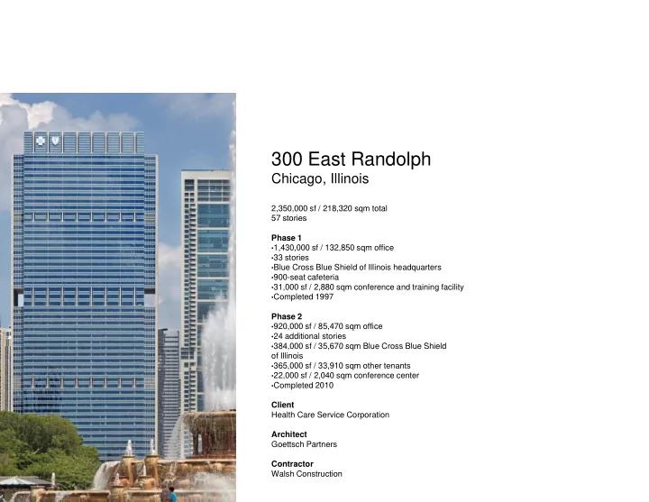
Chicago, Illinois
2,350,000 sf / 218,320 sqm total 57 stories 57 stories Phase 1
- 1,430,000 sf / 132,850 sqm office
- 33 stories
- Blue Cross Blue Shield of Illinois headquarters
- 900-seat cafeteria
- 31,000 sf / 2,880 sqm conference and training facility
- Completed 1997
Phase 2
- 920,000 sf / 85,470 sqm office
- 24 additional stories
- 384 000 sf / 35 670 sqm Blue Cross Blue Shield
- 384,000 sf / 35,670 sqm Blue Cross Blue Shield
- f Illinois
- 365,000 sf / 33,910 sqm other tenants
- 22,000 sf / 2,040 sqm conference center
- Completed 2010
Client Health Care Service Corporation Architect Goettsch Partners Contractor Walsh Construction Walsh Construction
SLIDE 2 The 300 East Randolph building is a two-phased, vertically expanded
- ffice tower located in downtown
- ffice tower located in downtown
- Chicago. The 57-story building
primarily serves as the headquarters for Health Care Service Corporation (HCSC) and its Blue Cross and Blue Shield of Illinois division. However, this headquarters facility was designed from the outset to accommodate multiple tenants over time—a “multitenant building, just time a multitenant building, just with a single tenant in mind,” according to the client.
SLIDE 3
Initially planned in 1994, the building is sited on a 2.3-acre lot at the north end of Grant Park, helping to define the street edge along Randolph g g p Street and with exceptional presence overlooking Millennium and Grant parks, Michigan Avenue and the lakefront.
SLIDE 4 The client had three main objectives for the project: improve efficiency of the organization enhance the quality the organization, enhance the quality
- f the working environment, and
provide flexibility to accommodate the future needs of the company. I ti l HCSC i d f ilit In particular, HCSC required a facility that would address their immediate space needs while providing a plan for long-term growth—without having to relocate. The successful design g met the company’s existing requirements and offered an innovative solution for future growth through vertical expansion, allowing the building to grow in line with the the building to grow, in line with the company, at a later date.
SLIDE 5
The plan to accommodate future expansion vertically would involve costs for purchasing additional FAR in phase t h th i two; however, the savings over purchasing additional land in order to build on adjacent property—another possible option—would be substantial.
SLIDE 6
The building’s 33-story, 1.43 million- g y square-foot first phase was completed in 1997.
SLIDE 7 The main entry faces south, identified with a steel-and-glass identified with a steel and glass canopy. A landscaped public plaza on the building’s north side provides an
- utdoor amenity while serving as
the roof over the company’s training center in the building podium.
SLIDE 8
An uplifting yellow pedestrian bridge connects an adjacent public parking garage underneath upper Randolph g g pp p Street to the building’s lower-level entry.
SLIDE 9
A concierge desk with an illuminated, elliptical disc above greets visitors and provides secured g p access through adjacent optical turnstiles.
SLIDE 10
Early on, the building owners recognized the potential of the building’s prominent southern façade, utilizing it as a billboard to ll th it h th f rally the community—whether for Chicago sports teams, worthy causes or, here, as a show of national pride.
SLIDE 11
In 2006—nearly a decade after the completion of phase one—the company decided to proceed with the initial plan, adding 24 stories p g and an additional 920,000 square feet atop the original building.
SLIDE 12 The fundamental mechanism behind the vertical expansion is a large, 150-foot-wide by 40-foot-deep atrium space on the building’s north p g side—primarily to accommodate elevators in both phases of
- development. Five open bays
accommodate four zones of elevators around a series of elevators around a series of circulation and breakout spaces in the center.
SLIDE 13
Phase one provided two eight-car banks of elevators to service the lower floors, along with fully open shafts to accept two additional eight fully open shafts to accept two additional eight- car banks for the high-rise in phase two. With the elevators organized accordingly along the north facade, the building's interior layout is unique, providing a consistent floor plan throughout and allowing for easy, efficient departmental moves.
SLIDE 14
The completion of phase one shows the full-height space of one of the two inner atrium bays. These bays became the location for the high- g rise elevator banks for the phase two expansion.
SLIDE 15
e building’s center atrium bay is reserved an open stair to facilitate inter-floor culation and every three floors the center elements add value and purpose, providing both a visual and physical connectivity within the company and an inviting inspiring space culation, and every three floors, the center y is fully built out and utilized for breakout unge and meeting space. Together, these the company, and an inviting, inspiring space for employees.
SLIDE 16 As high rises are seldom based on As high-rises are seldom based on an interior spatial concept, the atrium is unique. Designed to run the full-height of the building, it draws in abundant north light and g
- ffers a rare sense of the building’s
verticality from the interior.
SLIDE 17
The open stair is filled with daylight and encourages communication between floors, as well as use of the meeting space on every third level.
SLIDE 18 The open elevator shafts add to the transparency and porosity of the
- building. As the cabs and
counterweights traverse the atrium, g , they provide a kinetic “pulse” of the building’s activity.
SLIDE 19
To confirm that logistical plans To confirm that logistical plans would work in the expansion, the construction team tested certain items in advance. Here, on a weekend, a wood mockup of a 45- foot beam is brought through the foot beam is brought through the building’s front door to assure its fit as well as its ability to be lifted up through the atrium.
SLIDE 20 Given the complexity of ultimately assembling two tower cranes on top
- f the existing roof, the contractor
built a study model to plan the y p sequencing of both the two derrick cranes as well as the two tower cranes.
SLIDE 21
Here, the 17-ton and 35-ton derrick cranes are shown. These derricks helped erect the first tower crane, helped erect the first tower crane, which then was used to hoist and erect the second one.
SLIDE 22 The two tower cranes sit atop the expansion with the screen wall aro nd the phase one b ilding’s roof around the phase one building’s roof
- removed. This exposure provided
the existing cooling towers with necessary air circulation throughout construction until the new, more efficient cooling towers were installed on the new roof.
SLIDE 23
At completion in 2010, the building reaches its full height A construction photo from August 2008 shows the vertical expansion reaches its full height. 2008 shows the vertical expansion rising above the initial building—all while the building and company
SLIDE 24
Materials of glass, stainless steel and stone defined an initial aesthetic that was contemporary. These materials were also more easily matched over time in the expansion.
SLIDE 25
Designed to improve company efficiency, enhance the work environment and provide flexibility environment, and provide flexibility for growth in contiguous space, the 300 East Randolph building meets and well exceeds these goals. Through innovative design planning—and a collaborative team effort from start to finish—the building sits as a city icon and testament to its foresight, providing a seamless, integrated expression a seamless, integrated expression that now achieves its full height and appropriately fits in the Chicago skyline.
SLIDE 26