
2019/6/3 1
Software Engineering
1 Object-oriented Analysis and Design
Applying UML and Patterns
An Introduction to Object-oriented Analysis and Design and Iterative Development
Part III Elaboration Iteration I – Basic2
Software Engineering
2 Object-oriented Analysis and Design
Chapter 15 UML Interaction Diagrams
Software Engineering
3 Object-oriented Analysis and Design
Introduction
The UML includes interaction diagrams to illustrate
how objects interact via messages.
sequence and communication interaction diagrams. This chapter introduces the notation - view it as a
reference to skim through - while subsequent chapters focus on a more important question: What are key principles in OO design?
★
Software Engineering
4 Object-oriented Analysis and Design
Sequence and Communication Diagrams
The term interaction diagram is a generalization of two
more specialized UML diagram types:
sequence diagrams communication diagrams Both can express similar interactions A related diagram is the interaction overview diagram; provides a big-picture overview of how a set of interaction
diagrams are related in terms of logic and process-flow.
It's new to UML 2, and so it's too early to tell if it will be
practically useful.
Software Engineering
5 Object-oriented Analysis and Design
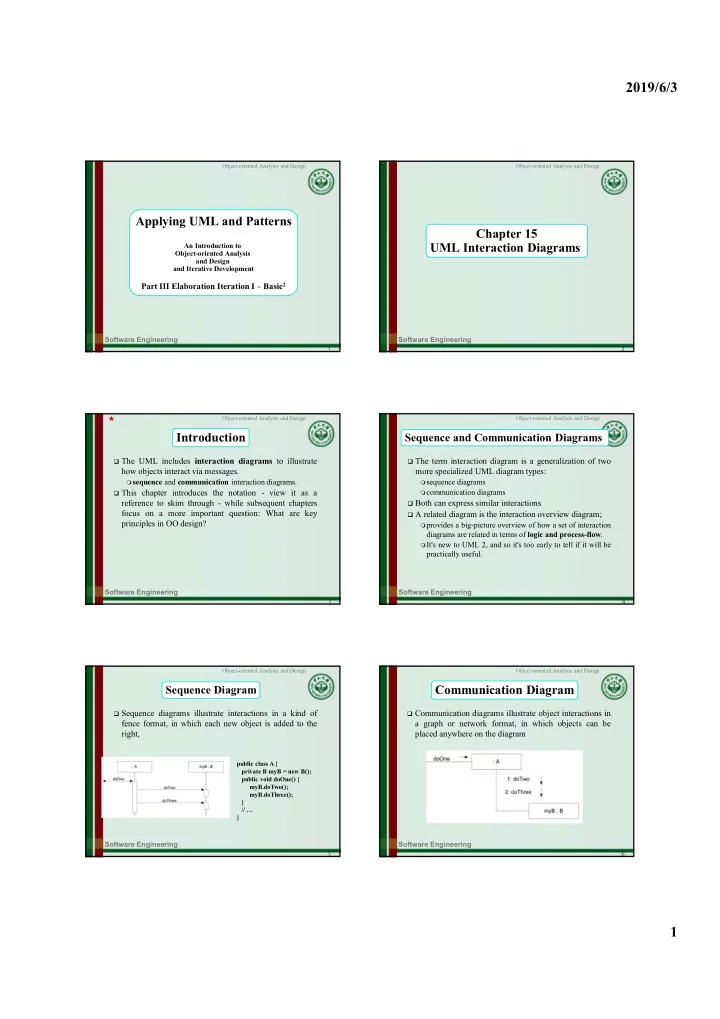
Sequence Diagram
Sequence diagrams illustrate interactions in a kind of
fence format, in which each new object is added to the right,
public class A { private B myB = new B(); public void doOne() { myB.doTwo(); myB.doThree(); } // … }
Software Engineering
6 Object-oriented Analysis and Design
Communication Diagram
Communication diagrams illustrate object interactions in