
SLIDE 1
1.10
www.kingslide.com
Undermount Slides
King Slide reserves the right to alter specifjcations of all the products without notice. If the entity is different from the illustration, please refer to the entity.
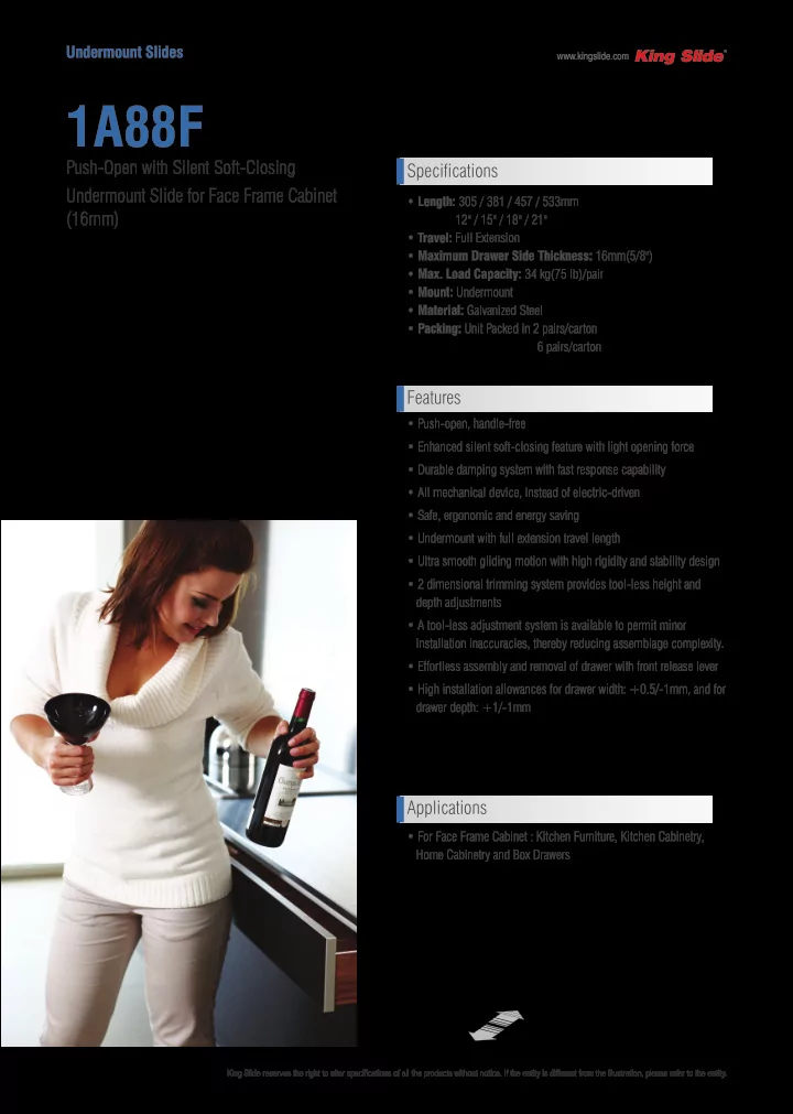
1A88F
- Length: 305 / 381 / 457 / 533mm
12" / 15" / 18" / 21"
- Travel: Full Extension
- Maximum Drawer Side Thickness: 16mm(5/8")
- Max. Load Capacity: 34 kg(75 lb)/pair
- Mount: Undermount
- Material: Galvanized Steel
- Packing: Unit Packed in 2 pairs/carton
6 pairs/carton
Push-Open with Silent Soft-Closing Undermount Slide for Face Frame Cabinet (16mm)
- Push-open, handle-free
- Enhanced silent soft-closing feature with light opening force
- Durable damping system with fast response capability
- All mechanical device, instead of electric-driven
- Safe, ergonomic and energy saving
- Undermount with full extension travel length
- Ultra smooth gliding motion with high rigidity and stability design
- 2 dimensional trimming system provides tool-less height and
depth adjustments
- A tool-less adjustment system is available to permit minor
installation inaccuracies, thereby reducing assemblage complexity.
- Effortless assembly and removal of drawer with front release lever
- High installation allowances for drawer width: +0.5/-1mm, and for
drawer depth: +1/-1mm
Specifications Features Applications
- For Face Frame Cabinet : Kitchen Furniture, Kitchen Cabinetry,
Home Cabinetry and Box Drawers