1 Links - Optical Links - Optical Single mode Optical Media - - PDF document

1
SMART_READER_LITE
LIVE PREVIEW

1 Links - Optical Links - Optical Single mode Optical Media - - PDF document

Direct Link Networks Direct Link Networks Two hosts connected directly No issues of contention, routing, Key points: Physical Connections Encoding and Modulation Framing Error Detection 9/6/06 UIUC -


slide-1
SLIDE 1

1 Direct Link Networks

9/6/06 UIUC - CS/ECE438, Fall 2006 2

Direct Link Networks

Two hosts connected directly

No issues of contention, routing, …

Key points:

Physical Connections

Encoding and Modulation

Framing

Error Detection

9/6/06 UIUC - CS/ECE438, Fall 2006 3

Internet Protocols

Physical Data Link

Hardware (network adapter)

Framing, error detection, medium access control Encoding Network Transport

Kernel software

Application Presentation Session

User-level software

9/6/06 UIUC - CS/ECE438, Fall 2006 4

Outline

 Hardware building blocks  Encoding  Framing

9/6/06 UIUC - CS/ECE438, Fall 2006 5

Hardware Building Blocks

 Nodes

Hosts: general purpose computers

Switches: typically special purpose hardware

Routers: varied

 Links

Copper wire with electronic signaling

Glass fiber with optical signaling

Wireless with electromagnetic (radio, infrared, microwave, signaling)

9/6/06 UIUC - CS/ECE438, Fall 2006 6
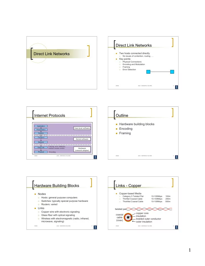
Links - Copper

Copper-based Media

Category 5 Twisted Pair 10-100Mbps 100m

ThinNet Coaxial Cable 10-100Mbps 200m

ThickNet Coaxial Cable 10-100Mbps 500m

twisted pair copper core insulation braided outer conductor

  • uter insulation

coaxial cable (coax)

slide-2
SLIDE 2

2

9/6/06 UIUC - CS/ECE438, Fall 2006 7

Links - Optical

 Optical Media

Multimode Fiber 100Mbps 2km

Single Mode Fiber 100-2400Mbps 40km glass core (the fiber) glass cladding plastic jacket

  • ptical

fiber

9/6/06 UIUC - CS/ECE438, Fall 2006 8

Links - Optical

Single mode

Lower attenuation (longer distances)

Lower dispersion (higher data rates)

Multimode fiber

Cheap to drive (LED’s) vs. lasers for single mode

Easier to terminate O(100 microns) thick core of multimode fiber (same frequency; colors for clarity) ~1 wavelength thick = ~1 micron core of single mode fiber

9/6/06 UIUC - CS/ECE438, Fall 2006 9

Links - Optical

 Advantages of optical communication

 Higher bandwidths  Superior attenuation properties  Immune from electromagnetic

interference

 No crosstalk between fibers  Thin, lightweight, and cheap (the fiber,

not the optical-electrical interfaces)

9/6/06 UIUC - CS/ECE438, Fall 2006 10

Leased Lines

 POTS

64Kbps

 ISDN

128Kbps

 ADSL

1.5-8Mbps/16-640Kbps

 Cable Modem 0.5-2Mbps  DS1/T1

1.544Mbps

 DS3/T3

44.736Mbps

 STS-1

51.840Mbps

 STS-3

155.250Mbps (ATM)

 STS-12

622.080Mbps (ATM)

9/6/06 UIUC - CS/ECE438, Fall 2006 11

Wireless

Cellular

AMPS 13Kbps 3km

PCS, GSM 300Kbps 3km

3G 2-3Mbps 3km

Wireless Local Area Networks (WLAN)

Infrared 4Mbps 10m

900Mhz 2Mbps 150m

2.4GHz 2Mbps 150m

2.4GHz 11Mbps 80m

Bluetooth 700Kbps 10m

Satellites

Geosynchronous satellite 600-1000 Mbps continent

Low Earth orbit (LEO) ~400 Mbps world

9/6/06 UIUC - CS/ECE438, Fall 2006 12

Encoding

 Problems with signal transmission

Attenuation: Signal power absorbed by medium

Dispersion: A discrete signal spreads in space

Noise: Random background “signals”

digital data (a string of symbols) digital data (a string of symbols) modulator demodulator

a string

  • f signals

modulator demodulator

slide-3
SLIDE 3

3

9/6/06 UIUC - CS/ECE438, Fall 2006 13

Encoding

 Goal:

Understand how to connect nodes in such a way that bits can be transmitted from one node to another

 Idea:

The physical medium is used to propagate signals

Modulate electromagnetic waves

Vary voltage, frequency, wavelength

Data is encoded in the signal

9/6/06 UIUC - CS/ECE438, Fall 2006 14

Analog vs. Digital Transmission

Advantages of digital transmission over analog

Reasonably low-error rates over arbitrary distances

Calculate/measure effects of transmission problems

Periodically interpret and regenerate signal

Simpler for multiplexing distinct data types (audio, video, e-mail, etc.)

Two examples based on modulator-demodulators (modems)

Electronic Industries Association (EIA) standard: RS-232(- C)

International Telecommunications Union (ITU) V.32 9600 bps modem standard

9/6/06 UIUC - CS/ECE438, Fall 2006 15

RS-232

Communication between computer and modem

Uses two voltage levels (+15V, -15V), a binary voltage encoding

Data rate limited to 19.2 kbps (RS-232-C); raised in later standards

Characteristics

Serial: one signaling wire, one bit at a time

Asynchronous: line can be idle, clock generated from data

Character-based: send data in 7- or 8-bit characters

9/6/06 UIUC - CS/ECE438, Fall 2006 16

RS-232 Timing Diagram

idle start 1 1 1 stop idle

  • 15

+ +15

Time Voltage

9/6/06 UIUC - CS/ECE438, Fall 2006 17

RS-232

One bit per clock

Voltage never returns to 0V

0V is a dead/disconnected line

  • 15V is both idle and “1”

initiates send by pushing to 15V for one clock (start bit)

Minimum delay between character transmissions

Idle for one clock at -15V (stop bit)

One character leads to 2+ voltage transitions

Total of 9 bits for 7 bits of data (78% efficient)

Start and stop bits also provide framing

9/6/06 UIUC - CS/ECE438, Fall 2006 18

Voltage Encoding

 Common binary voltage encodings

 Non-return to zero (NRZ)  NRZ inverted (NRZI)  Manchester (used by IEEE 802.3—10

Mbps Ethernet)

 4B/5B

slide-4
SLIDE 4

4

9/6/06 UIUC - CS/ECE438, Fall 2006 19

Non-Return to Zero (NRZ)

Signal to Data

High  1

Low 

Comments

Transitions maintain clock synchronization

Long strings of 0s confused with no signal

Long strings of 1s causes baseline wander

Both inhibit clock recovery

Bits 1 1 1 1 1 1 1 NRZ

9/6/06 UIUC - CS/ECE438, Fall 2006 20

Non-Return to Zero Inverted (NRZI)

 Signal to Data

Transition  1

Maintain 

Bits 1 1 1 1 1 1 1 NRZ NRZI

 Comments

Strings of 0’s still a problem

9/6/06 UIUC - CS/ECE438, Fall 2006 21

Manchester Encoding

Signal to Data

XOR NRZ data with clock

High to low transition  1

Low to high transition 

Comments

Solves clock recovery problem

Only 50% efficient ( 1/2 bit per transition) Bits 1 1 1 1 1 1 1 NRZ Clock Manchester

9/6/06 UIUC - CS/ECE438, Fall 2006 22

4B/5B

 Signal to Data

Encode every 4 consecutive bits as a 5 bit symbol

 Symbols

At most 1 leading 0

At most 2 trailing 0s

Never more than 3 consecutive 0s

Transmit with NRZI

 Comments

80% efficient

9/6/06 UIUC - CS/ECE438, Fall 2006 23

Binary Voltage Encodings

Problem with binary voltage (square wave) encodings:

Wide frequency range required, implying

Significant dispersion

Uneven attenuation 

Prefer to use narrow frequency band (carrier frequency)

Types of modulation

Amplitude (AM)

Frequency (FM)

Phase/phase shift

Combinations of these

9/6/06 UIUC - CS/ECE438, Fall 2006 24

Amplitude Modulation

1

idle

slide-5
SLIDE 5

5

9/6/06 UIUC - CS/ECE438, Fall 2006 25

Frequency Modulation

1

idle

9/6/06 UIUC - CS/ECE438, Fall 2006 26

Phase Modulation

1

idle

9/6/06 UIUC - CS/ECE438, Fall 2006 27

Phase Modulation

108º difference in phase collapse for 108º shift

phase shift in carrier frequency

9/6/06 UIUC - CS/ECE438, Fall 2006 28

Phase Modulation Algorithm

 Send carrier frequency

for one period

Perform phase shift

Shift value encodes symbol

Value in range [0, 360º)

Multiple values for multiple symbols

Represent as circle

0º 45º 90º 315º 270º 135º 225º 180º 8-symbol example

9/6/06 UIUC - CS/ECE438, Fall 2006 29

V.32 9600 bps

 Communication between modems  Analog phone line  Uses a combination of amplitude and

phase modulation

 Known as Quadrature Amplitude

Modulation (QAM)

 Sends one of 16 signals each clock

cycle

9/6/06 UIUC - CS/ECE438, Fall 2006 30

Constellation Pattern for V.32 QAM

45º 15º For a given symbol: Perform phase shift and change to new amplitude

slide-6
SLIDE 6

6

9/6/06 UIUC - CS/ECE438, Fall 2006 31

Quadrature Amplitude Modulation (QAM)

 Same algorithm as

phase modulation

 Can also change

signal amplitude

 2-dimensional

representation

Angle is phase shift

Radial distance is new amplitude 45º 15º 16-symbol example (V.32)

9/6/06 UIUC - CS/ECE438, Fall 2006 32

Comments on V.32

 V.32 transmits at 2400 baud

 i.e., 2,400 symbols per second

 Each symbol contains log2 16 = 4 bits

 Data rate is thus 4 x 2400 = 9600 bps

 Points in constellation diagram

 Chosen to maximize error detection  Process called trellis coding

9/6/06 UIUC - CS/ECE438, Fall 2006 33

Generalizing the Examples

 What limits baud rate?  What data rate can a channel sustain?  How is data rate related to bandwidth?  How does noise affect these bounds?  What else can limit maximum data

rate?

9/6/06 UIUC - CS/ECE438, Fall 2006 34

What Limits Baud Rate?

 Baud rates are typically limited by electrical

signaling properties.

 No matter how small the voltage or how

short the wire, changing voltages takes time.

 Electronics are slow compared to optics.  Note that baud rate can be as high as twice

the frequency (bandwidth) of communication; one cycle can contain two symbols.

9/6/06 UIUC - CS/ECE438, Fall 2006 35

What Data Rate can a Channel Sustain? How is Data Rate Related to Bandwidth?

 Transmitting N distinct signals over a

noiseless channel with bandwidth B, we can achieve at most a data rate of 2B log2 N

 This observation is a form of Nyquist’s

Sampling Theorem (H. Nyquist, 1920’s)

We can reconstruct any waveform with no frequency component above some frequency F using only samples taken at frequency 2F.

9/6/06 UIUC - CS/ECE438, Fall 2006 36

What else (Besides Noise) can Limit Maximum Data Rate?

 Transitions between symbols

Introduce high-frequency components into the transmitted signal

Such components cannot be recovered (by Nyquist’s Theorem), and some information is lost

 Examples

Phase modulation

Single frequency (with different phases) for each symbol

Transitions can require very high frequencies

slide-7
SLIDE 7

7

9/6/06 UIUC - CS/ECE438, Fall 2006 37

How does Noise affect these Bounds?

In-band (not high-frequency) noise blurs the symbols, reducing the number of symbols that can be reliably distinguished.

In 1948, Claude Shannon extended Nyquist’s work to channels with additive white Gaussian noise (a good model for thermal noise): channel capacity C = B log2 (1 + S/N) where: B is the channel bandwidth S/N is the ratio between signal power and in-band noise power

9/6/06 UIUC - CS/ECE438, Fall 2006 38

Summary of Encoding

Problems: attenuation, dispersion, noise

Digital transmission allows periodic regeneration

Variety of binary voltage encodings

High frequency components limit to short range

More voltage levels provide higher data rate

Carrier frequency and modulation

Amplitude, frequency, phase, and combinations

Quadrature amplitude modulation: amplitude and phase, many signals

Nyquist (noiseless) and Shannon (noisy) limits on data rates

9/6/06 UIUC - CS/ECE438, Fall 2006 39

Framing

 Encoding translates symbols to signals  Framing demarcates units of transfer

Separates continuous stream of bits into frames

Marks start and end of each frame

digital data (a string of symbols) digital data (a string of symbols) modulator demodulator

a string

  • f signals

9/6/06 UIUC - CS/ECE438, Fall 2006 40

Framing

 Demarcates units of transfer  Goal

 Enable nodes to exchange blocks of data

 Challenge

 How can we determine exactly what set

  • f bits constitute a frame?

 How do we determine the beginning and

end of a frame?

9/6/06 UIUC - CS/ECE438, Fall 2006 41

Framing

 Synchronization recovery

Breaks up continuous streams of unframed bytes

Recall RS-232 start and stop bits

 Link multiplexing

Multiple hosts on shared medium

Simplifies multiplexing of logical channels

 Efficient error detection

Per-frame error checking and recovery

9/6/06 UIUC - CS/ECE438, Fall 2006 42

Framing

 Approaches

Sentinel (like C strings)

Length-based (like Pascal strings)

Clock based

 Characteristics

Bit- or byte-oriented

Fixed or variable length

Data-dependent or data-independent length

slide-8
SLIDE 8

8

9/6/06 UIUC - CS/ECE438, Fall 2006 43

Sentinel-Based Framing

 End of Frame

 Marked with a special byte or bit pattern  Requires stuffing  Frame length is data-dependent  Challenge  Frame marker may exist in data

 Examples:

 ARPANET IMP-IMP, HDLC, PPP, IEEE

802.4 (token bus)

9/6/06 UIUC - CS/ECE438, Fall 2006 44

ARPANET IMP-IMP

Interface Message processors (IMPs)

Packet switching nodes in the original ARPANET

Byte oriented, Variable length, Data dependent

Frame marker bytes:

STX/ETX start of text/end of text

DLE data link escape

Byte Stuffing

DLE byte in data sent as two DLE bytes back-to-back DLE STX DLE ETX BODY

HEADER

0x48 0x69 DLE DLE 0x69 0x48 DLE

9/6/06 UIUC - CS/ECE438, Fall 2006 45

BISYNC

 BInary SYNchronous Communication

Developed by IBM in late 1960’s

Byte oriented, Variable length, Data dependent

Frame marker bytes:

STX/ETX start of text/end of text

DLE data link escape

Byte Stuffing

ETX/DLE bytes in data prefixed with DLE’s

ETX STX ETX BODY

HEADER

0x48 0x69 ETX DLE 0x69 0x48

9/6/06 UIUC - CS/ECE438, Fall 2006 46

High-Level Data Link Control Protocol (HDLC)

 Bit oriented, Variable length, Data-

dependent

 Frame Marker

01111110

 Bit Stuffing

Insert 0 after pattern 011111 in data

Example

01111110 end of frame

01111111 error! lose one or two frames

9/6/06 UIUC - CS/ECE438, Fall 2006 47

IEEE 802.4 (token bus)

Alternative to Ethernet (802.3) with fairer arbitration

End of frame marked by encoding violation,

i.e., physical signal not used by valid data symbol

Recall Manchester encoding

low-high means “0”

high-low means “1”

low-low and high-high are invalid

802.4:

byte-oriented, variable-length, data-independent

Another example:

Fiber Distributed Data Interface (FDDI) uses 4B/5B

Technique also applicable to bit-oriented framing

9/6/06 UIUC - CS/ECE438, Fall 2006 48

Length-Based Framing

 End of frame

Calculated from length sent at start of frame

Challenge: Corrupt length markers

 Examples

DECNET’s DDCMP:

Byte-oriented, variable-length

RS-232 framing:

Bit-oriented, implicit fixed-length

LENGTH

BODY

HEADER

slide-9
SLIDE 9

9

9/6/06 UIUC - CS/ECE438, Fall 2006 49

Clock-Based Framing

 Continuous stream of fixed-length frames  Clocks must remain synchronized  STS-1 frames - 125µs long

No bit or byte stuffing

 Example:

Synchronous Optical Network (SONET)

 Problems:

Frame synchronization

Clock synchronization

9/6/06 UIUC - CS/ECE438, Fall 2006 50

SONET

Frame Synchronization

2-byte synchronization pattern at start of each frame

Wait for repeated pattern in same place

Clock Synchronization

Data scrambled and transmitted with NRZ

Creates transitions

Reduces probability of false synch pattern

… … … … … … … … …

Overhead Payload 9 rows 90 columns

9/6/06 UIUC - CS/ECE438, Fall 2006 51

SONET

Frames (all STS formats) are 125 µsec long

Problem: how to recover frame synchronization

2-byte synchronization pattern starts each frame (unlikely to occur in data)

Wait until pattern appears in same place repeatedly

Problem: how to maintain clock synchronization

NRZ encoding, data scrambled (XOR’d) with 127-bit pattern

Creates transitions

Also reduces chance of finding false sync. pattern

9/6/06 UIUC - CS/ECE438, Fall 2006 52

SONET

 A single SONET frame may contain

multiple smaller SONET frames

 Bytes from multiple SONET frames

are interleaved to ensure pacing

HDR HDR HDR HDR STS-1 STS-1 STS-1 STS-3

9/6/06 UIUC - CS/ECE438, Fall 2006 53

SONET

STS-1 merged bytewise round-robin into STS-3

Unmerged (single-source) format called STS-3c

Problem: simultaneous synchronization of many distributed clocks

not too difficult to synchronize clocks such that first byte of all incoming flows arrives just before sending first 3 bytes

  • f outgoing flow

67B 249B 151B

9/6/06 UIUC - CS/ECE438, Fall 2006 54

SONET

... but now try to synchronize this network’s clocks

slide-10
SLIDE 10

10

9/6/06 UIUC - CS/ECE438, Fall 2006 55

SONET

One alternative to synchronization is to delay each frame by some fraction of a 125 microsecond period at each switch (i.e., until the next outgoing frame starts). Delays add up quickly...

Or, worse, a network with cycles.

9/6/06 UIUC - CS/ECE438, Fall 2006 56

SONET

 Problem:

Clock synchronization across multiple machines

 Solution

Allow payload to float across frame boundaries

Part of overhead specifies first byte of payload … … … … … … … … …