1 Switch: frame filtering/forwarding Switch: self-learning Source: - - PDF document

1
SMART_READER_LITE
LIVE PREVIEW

1 Switch: frame filtering/forwarding Switch: self-learning Source: - - PDF document

The Data Link Layer Addressing Last time Our goals: different address scheme in different link layer services understand principles layers error detection, correction behind data link layer services: multiple access


slide-1
SLIDE 1

1

7/10-08 Datakommunikation - Jonny Pettersson, UmU

The Data Link Layer

Our goals:

understand principles

behind data link layer services:

error detection,

correction

sharing a broadcast

channel: multiple access

link layer addressing reliable data transfer,

flow control: done! instantiation and

implementation of various link layer technologies

Last time

link layer services error detection, correction multiple access protocols and

LANs

link layer addressing, ARP,

DHCP

Ethernet

Today

hubs and switches PPP

7/10-08 Datakommunikation - Jonny Pettersson, UmU

Addressing

different address scheme in different

layers

application layer: host names (transport layer: port number) network layer: IP-addresses link layer: LAN addresses

translation mechanisms

DNS ARP

7/10-08 Datakommunikation - Jonny Pettersson, UmU

Hubs

… physical-layer (“dumb”) repeaters:

bits coming in one link go out all other links at

same rate

all nodes connected to hub can collide with one

another

no frame buffering no CSMA/CD at hub: host NICs detect

collisions

twisted pair hub

7/10-08 Datakommunikation - Jonny Pettersson, UmU

Switch

link-layer device: smarter than hubs, take

active role

store, forward Ethernet frames examine incoming frame’s MAC address,

selectively forward frame to one-or-more

  • utgoing links when frame is to be forwarded on

segment, uses CSMA/CD to access segment transparent

hosts are unaware of presence of switches

plug-and-play, self-learning

switches do not need to be configured

7/10-08 Datakommunikation - Jonny Pettersson, UmU

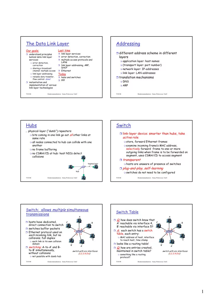
Switch: allows multiple simultaneous transmissions

hosts have dedicated,

direct connection to switch

switches buffer packets Ethernet protocol used on

each incoming link, but no collisions; full duplex

each link is its own collision

domain switching: A-to-A’ and B-

to-B’ simultaneously, without collisions

not possible with dumb hub

A A’ B B’ C C’ switch with six interfaces (1,2,3,4,5,6) 1 2 3 4 5 6

7/10-08 Datakommunikation - Jonny Pettersson, UmU

Switch Table

Q: how does switch know that

A’ reachable via interface 4, B’ reachable via interface 5?

A: each switch has a switch

table, each entry:

MAC address of host, interface

to reach host, time stamp looks like a routing table! Q: how are entries created,

maintained in switch table?

something like a routing

protocol?

A A’ B B’ C C’ switch with six interfaces (1,2,3,4,5,6) 1 2 3 4 5 6

slide-2
SLIDE 2

2

7/10-08 Datakommunikation - Jonny Pettersson, UmU

Switch: self-learning

switch learns which hosts

can be reached through which interfaces

when frame received,

switch “learns” location of sender: incoming LAN segment

records sender/location

pair in switch table

A A’ B B’ C C’ 1 2 3 4 5 6 A A’

Source: A Dest: A’

MAC addr interface TTL Switch table (initially empty) A 1 60

7/10-08 Datakommunikation - Jonny Pettersson, UmU

Switch: frame filtering/forwarding

When frame received:

  • 1. record link associated with sending host
  • 2. index switch table using MAC dest address
  • 3. if entry found for destination

then { if dest on segment from which frame arrived then drop the frame else forward the frame on interface indicated } else flood forward on all but the interface

  • n which the frame arrived

7/10-08 Datakommunikation - Jonny Pettersson, UmU

Self-learning, forwarding: example

A A’ B B’ C C’ 1 2 3 4 5 6 A A’

Source: A Dest: A’

MAC addr interface TTL Switch table (initially empty) A 1 60 A A’ A A’ A A’ A A’ A A’

frame destination

unknown: flood

A’ A

destination A

location known:

A’ 4 60

selective send

7/10-08 Datakommunikation - Jonny Pettersson, UmU

Interconnecting switches

switches can be connected together

A B

Q: sending from A to G - how does S1 know to

forward frame destined to F via S4 and S3?

A: self learning! (works exactly the same as in

single-switch case!)

S1 C D E F S2 S4 S3 H I G

7/10-08 Datakommunikation - Jonny Pettersson, UmU

Switches vs. Routers

both store-and-forward devices

routers: network layer devices (examine network layer

headers)

switches are link layer devices

routers maintain routing tables, implement routing

algorithms

switches maintain switch tables, implement

filtering, learning algorithms

7/10-08 Datakommunikation - Jonny Pettersson, UmU

Point to Point Data Link Control

  • ne sender, one receiver, one link: easier than

broadcast link:

no Media Access Control no need for explicit MAC addressing e.g., dialup link, ISDN line

popular point-to-point DLC protocols:

PPP (point-to-point protocol) HDLC: High level data link control (Data link

used to be considered “high layer” in protocol stack!)

slide-3
SLIDE 3

3

7/10-08 Datakommunikation - Jonny Pettersson, UmU

Virtualization of networks

Virtualization of resources: a powerful abstraction in systems engineering:

computing examples:

virtual memory virtual devices Virtual machines: e.g., java

layering of abstractions: don’t sweat the details of

the lower layer, only deal with lower layers abstractly

The Internet: virtualizing networks

1974: multiple unconnected nets

ARPAnet data-over-cable networks packet satellite network (Aloha) packet radio network

… differing in:

addressing conventions packet formats error recovery routing

ARPAnet satellite net

"A Protocol for Packet Network Intercommunication",

  • V. Cerf, R. Kahn, IEEE Transactions on Communications,

May, 1974, pp. 637

  • 6

48.

7/10-08 Datakommunikation - Jonny Pettersson, UmU

The Internet: virtualizing networks

ARPAnet satellite net gateway

Internetwork layer (IP):

addressing: internetwork

appears as a single, uniform entity, despite underlying local network heterogeneity

network of networks

Gateway:

“embed internetwork packets in

local packet format or extract them”

route (at internetwork level) to

next gateway

7/10-08 Datakommunikation - Jonny Pettersson, UmU

Cerf & Kahn’s Internetwork Architecture

What is virtualized?

two layers of addressing: internetwork and local

network

new layer (IP) makes everything homogeneous at

internetwork layer

underlying local network technology

cable satellite 56K telephone modem ATM, MPLS

… “invisible” at internetwork layer. Looks like a link layer technology to IP!

7/10-08 Datakommunikation - Jonny Pettersson, UmU

The Data Link Layer

Our goals:

understand principles

behind data link layer services:

error detection,

correction

sharing a broadcast

channel: multiple access

link layer addressing reliable data transfer,

flow control: done! instantiation and

implementation of various link layer technologies

Last time

link layer services error detection, correction multiple access protocols and

LANs

link layer addressing, ARP,

DHCP

Ethernet

Today

hubs and switches PPP

Next

Wireless and Mobile Networks

7/10-08 Datakommunikation - Jonny Pettersson, UmU

Chapter 6: Wireless and Mobile Networks

Background:

# wireless (mobile) phone subscribers now

exceeds # wired phone subscribers!

computer nets: laptops, palmtops, PDAs,

Internet-enabled phone promise anytime untethered Internet access

two important (but different) challenges

wireless: communication over wireless link mobility: handling the mobile user who changes point

  • f attachment to network
slide-4
SLIDE 4

4

7/10-08 Datakommunikation - Jonny Pettersson, UmU

Chapter 6 outline

6.1 Introduction Wireless

6.2 Wireless links,

characteristics

CDMA

6.3 IEEE 802.11

wireless LANs (“wi-fi”)

6.4 Cellular Internet

Access

architecture standards (e.g., GSM)

Mobility

6.5 Principles:

addressing and routing to mobile users

6.6 Mobile IP 6.7 Handling mobility in

cellular networks

6.8 Mobility and higher-

layer protocols 6.9 Summary

7/10-08 Datakommunikation - Jonny Pettersson, UmU

Elements of a wireless network

network infrastructure

wireless hosts

laptop, PDA, IP phone run applications may be stationary

(non-mobile) or mobile

wireless does not

always mean mobility

7/10-08 Datakommunikation - Jonny Pettersson, UmU

Elements of a wireless network

network infrastructure

base station

typically connected to

wired network

relay - responsible

for sending packets between wired network and wireless host(s) in its “area”

e.g., cell towers,

802.11 access points

7/10-08 Datakommunikation - Jonny Pettersson, UmU

Elements of a wireless network

network infrastructure

wireless link

typically used to

connect mobile(s) to base station

also used as backbone

link

multiple access

protocol coordinates link access

various data rates,

transmission distance

7/10-08 Datakommunikation - Jonny Pettersson, UmU

Characteristics of selected wireless link standards

Indoor

10-30m

Outdoor

50-200m

Mid-range

  • utdoor

200m – 4 Km

Long-range

  • utdoor

5Km – 20 Km

.056 .384 1 4 5-11 54

IS-95, CDMA, GSM

2G

UMTS/WCDMA, CDMA2000

3G

802.15 802.11b 802.11a,g UMTS/WCDMA-HSPDA, CDMA2000-1xEVDO

3G cellular enhanced

802.16 (WiMAX) 802.11a,g point-to-point

200

802.11n

Data rate (Mbps)

data

7/10-08 Datakommunikation - Jonny Pettersson, UmU

Elements of a wireless network

network infrastructure

infrastructure mode

base station connects

mobiles into wired network

handoff: mobile

changes base station providing connection into wired network

slide-5
SLIDE 5

5

7/10-08 Datakommunikation - Jonny Pettersson, UmU

Elements of a wireless network

Ad hoc mode

no base stations nodes can only

transmit to other nodes within link coverage

nodes organize

themselves into a network: route among themselves

7/10-08 Datakommunikation - Jonny Pettersson, UmU

Wireless Link Characteristics (1)

Differences from wired link ….

decreased signal strength: radio signal

attenuates as it propagates through matter (path loss)

interference from other sources: standardized

wireless network frequencies (e.g., 2.4 GHz) shared by other devices (e.g., phone); devices (motors) interfere as well

multipath propagation: radio signal reflects off

  • bjects ground, arriving at destination at

slightly different times …. make communication across (even a point to point) wireless link much more “difficult”

7/10-08 Datakommunikation - Jonny Pettersson, UmU

Wireless Link Characteristics (2)

SNR: signal-to-noise ratio

larger SNR – easier to

extract signal from noise (a “good thing”)

SNR versus BER tradeoffs

given physical layer:

increase power -> increase SNR->decrease BER

given SNR: choose physical

layer that meets BER requirement, giving highest thruput

  • SNR may change with

mobility: dynamically adapt physical layer (modulation technique, rate)

10 20 30 40

QAM256 (8 Mbps) QAM16 (4 Mbps) BPSK (1 Mbps) SNR(dB) BER

10-1 10-2 10-3 10-5 10-6 10-7 10-4

7/10-08 Datakommunikation - Jonny Pettersson, UmU

Wireless network characteristics

Multiple wireless senders and receivers create additional problems (beyond multiple access):

A B C

Hidden terminal problem

B, A hear each other B, C hear each other A, C can not hear each other

means A, C unaware of their interference at B

A B C

A’s signal strength

space

C’s signal strength

Signal fading:

B, A hear each other B, C hear each other A, C can not hear each other

interferring at B

7/10-08 Datakommunikation - Jonny Pettersson, UmU

IEEE 802.11 Wireless LAN

802.11b

2.4-5 GHz unlicensed spectrum up to 11 Mbps

802.11a

5-6 GHz range up to 54 Mbps

802.11g

2.4-5 GHz range up to 54 Mbps

802.11n: multiple antennae

2.4-5 GHz range up to 200 Mbps

all use CSMA/CA for multiple access all have base-station and ad-hoc network versions

7/10-08 Datakommunikation - Jonny Pettersson, UmU

802.11 LAN architecture

wireless host communicates

with base station

base station = access

point (AP)

Basic Service Set (BSS)

(aka “cell”) in infrastructure mode contains:

wireless hosts access point (AP): base

station

ad hoc mode: hosts only

BSS 1 BSS 2 Internet hub, switch

  • r router

AP AP

slide-6
SLIDE 6

6

7/10-08 Datakommunikation - Jonny Pettersson, UmU

802.11: Channels, association

802.11b: 2.4GHz-2.485GHz spectrum divided into

11 channels at different frequencies

AP admin chooses frequency for AP interference possible: channel can be same as

that chosen by neighboring AP! host: must associate with an AP

scans channels, listening for beacon frames

containing AP’s name (SSID) and MAC address

selects AP to associate with may perform authentication [Chapter 8] will typically run DHCP to get IP address in AP’s

subnet

7/10-08 Datakommunikation - Jonny Pettersson, UmU

802.11: passive/active scanning

AP 2 AP 1 H1 BBS 2 BBS 1

1 2 2 3 4

Active Scanning:

(1) Probe Request frame broadcast from H1 (2) Probes response frame sent from APs (3) Association Request frame sent: H1 to selected AP (4) Association Response frame sent: H1 to selected AP

AP 2 AP 1 H1 BBS 2 BBS 1

1 2 3 1

Passive Scanning:

(1) beacon frames sent from APs (2) association Request frame sent: H1 to selected AP (3) association Response frame sent: H1 to selected AP

7/10-08 Datakommunikation - Jonny Pettersson, UmU

IEEE 802.11: multiple access

avoid collisions: 2+ nodes transmitting at same time 802.11: CSMA - sense before transmitting

don’t collide with ongoing transmission by other node

802.11: no collision detection!

difficult to receive (sense collisions) when transmitting due

to weak received signals (fading)

can’t sense all collisions in any case: hidden terminal, fading goal: avoid collisions: CSMA/C(ollision)A(voidance)

A B C A B C

A’s signal strength

space

C’s signal strength 7/10-08 Datakommunikation - Jonny Pettersson, UmU

IEEE 802.11 MAC Protocol: CSMA/CA

802.11 sender 1 if sense channel idle for DIFS then

transmit entire frame (no CD) 2 if sense channel busy then start random backoff time timer counts down while channel idle transmit when timer expires if no ACK, increase random backoff interval, repeat 2

802.11 receiver

  • if frame received OK

return ACK after SIFS (ACK needed due to hidden terminal problem)

sender receiver

DIFS

data

SIFS

ACK

7/10-08 Datakommunikation - Jonny Pettersson, UmU

Avoiding collisions (more)

idea: allow sender to “reserve” channel rather than random

access of data frames: avoid collisions of long data frames

sender first transmits small request-to-send (RTS) packets

to BS using CSMA

RTSs may still collide with each other (but they’re short)

BS broadcasts clear-to-send CTS in response to RTS RTS/CTS heard by all nodes

sender transmits data frame

  • ther stations defer transmissions

Avoid data frame collisions completely using small reservation packets!

7/10-08 Datakommunikation - Jonny Pettersson, UmU

Collision Avoidance: RTS-CTS exchange

AP A B time RTS(A) RTS(B) RTS(A) C T S ( A ) CTS(A) DATA (A) A C K ( A ) ACK(A) reservation collision defer

slide-7
SLIDE 7

7

7/10-08 Datakommunikation - Jonny Pettersson, UmU

hub or switch AP 2 AP 1 H1 BBS 2 BBS 1

802.11: mobility within same subnet

router

H1 remains in same IP

subnet: IP address can remain same

switch: which AP is

associated with H1?

self-learning (Ch. 5):

switch will see frame from H1 and “remember” which switch port can be used to reach H1

7/10-08 Datakommunikation - Jonny Pettersson, UmU Mobile Switching Center

Public telephone network, and Internet

Mobile Switching Center

Components of cellular network architecture

connects cells to wide area net manages call setup handles mobility

MSC

covers geographical

region

base station (BS)

analogous to 802.11 AP

mobile users attach

to network through BS

air-interface:

physical and link layer protocol between mobile and BS

cell wired network

7/10-08 Datakommunikation - Jonny Pettersson, UmU

Cellular networks: the first hop

Two techniques for sharing mobile-to-BS radio spectrum

combined FDMA/TDMA:

divide spectrum in frequency channels, divide each channel into time slots

CDMA: code division

multiple access

frequency bands time slots

7/10-08 Datakommunikation - Jonny Pettersson, UmU

Cellular standards:

2G systems: voice channels

IS-136, GSM, IS-95

2.5 G systems: voice and data channels

GPRS, EDGE, CDMA-2000

3G systems: voice/data

UMTS, CDMA-2000 with EVDO

IS-136 GSM IS-95 G P R S E D G E CDMA-2000 UMTS T D M A / F D M A Don’t drown in a bowl

  • f alphabet soup: use this

for reference only

7/10-08 Datakommunikation - Jonny Pettersson, UmU

What is mobility?

spectrum of mobility, from the network perspective:

no mobility high mobility

mobile wireless user, using same access point mobile user, passing through multiple access point while maintaining ongoing connections (like cell

phone)

mobile user, connecting/ disconnecting from network using DHCP

7/10-08 Datakommunikation - Jonny Pettersson, UmU

Mobility: Vocabulary

home network: permanent “home” of mobile

(e.g., 128.119.40/24)

Permanent address: address in home network, can always be used to reach mobile

e.g., 128.119.40.186

home agent: entity that will perform mobility functions on behalf of mobile, when mobile is remote

wide area network

correspondent

slide-8
SLIDE 8

8

7/10-08 Datakommunikation - Jonny Pettersson, UmU

Mobility: more vocabulary

Care-of-address: address in visited network

(e.g., 79,129.13.2) wide area network

visited network: network in which mobile currently resides (e.g., 79.129.13/24) Permanent address: remains constant (e.g., 128.119.40.186) foreign agent: entity in visited network that performs mobility functions on behalf of mobile correspondent: wants to communicate with mobile

7/10-08 Datakommunikation - Jonny Pettersson, UmU

Mobility: approaches

Let routing handle it: routers advertise permanent

address of mobile-nodes-in-residence via usual routing table exchange

routing tables indicate where each mobile located no changes to end-systems

Let end-systems handle it:

indirect routing: communication from

correspondent to mobile goes through home agent, then forwarded to remote

direct routing: correspondent gets foreign

address of mobile, sends directly to mobile

not scalable to millions of mobiles

7/10-08 Datakommunikation - Jonny Pettersson, UmU

Mobility: registration

End result:

Foreign agent knows about mobile Home agent knows location of mobile

wide area network

home network visited network

1

mobile contacts foreign agent on entering visited network

2

foreign agent contacts home agent home: “this mobile is resident in my network”

7/10-08 Datakommunikation - Jonny Pettersson, UmU

Mobility via Indirect Routing

wide area network

home network visited network

3 2 4 1 correspondent addresses packets using home address

  • f mobile

home agent intercepts packets, forwards to foreign agent foreign agent receives packets, forwards to mobile mobile replies directly to correspondent

7/10-08 Datakommunikation - Jonny Pettersson, UmU

Indirect Routing: comments

Mobile uses two addresses:

permanent address: used by correspondent (hence

mobile location is transparent to correspondent)

care-of-address: used by home agent to forward

datagrams to mobile

foreign agent functions may be done by mobile itself triangle routing: correspondent-home-network-

mobile

inefficient when

correspondent, mobile are in same network

slide-9
SLIDE 9

9

7/10-08 Datakommunikation - Jonny Pettersson, UmU

Indirect Routing: moving between networks

suppose mobile user moves to another

network

registers with new foreign agent new foreign agent registers with home agent home agent update care-of-address for mobile packets continue to be forwarded to mobile (but

with new care-of-address) mobility, changing foreign networks

transparent: on going connections can be maintained!

7/10-08 Datakommunikation - Jonny Pettersson, UmU

Mobility via Direct Routing

wide area network

home network visited network

4 2 4 1 correspondent requests, receives foreign address of mobile correspondent forwards to foreign agent foreign agent receives packets, forwards to mobile mobile replies directly to correspondent 3

7/10-08 Datakommunikation - Jonny Pettersson, UmU

Mobility via Direct Routing: comments

  • vercome triangle routing problem

non-transparent to correspondent:

correspondent must get care-of-address from home agent

what if mobile changes visited network?

7/10-08 Datakommunikation - Jonny Pettersson, UmU

wide area network

1

foreign net visited at session start anchor foreign agent

2 4

new foreign agent

3 5

correspondent agent correspondent new foreign network

Accommodating mobility with direct routing

anchor foreign agent: FA in first visited network data always routed first to anchor FA when mobile moves: new FA arranges to have data

forwarded from old FA (chaining)

7/10-08 Datakommunikation - Jonny Pettersson, UmU

Chapter 6 Summary

Wireless

wireless links:

capacity, distance channel impairments CDMA

IEEE 802.11 (“wi-fi”)

CSMA/CA reflects

wireless channel characteristics cellular access

architecture standards (e.g., GSM,

CDMA-2000, UMTS)

Mobility

principles: addressing,

routing to mobile users

home, visited networks direct, indirect routing care-of-addresses