
SLIDE 1
1.101: Introduction to CEE Design Introduction to Shop Drawings - - PowerPoint PPT Presentation
1.101: Introduction to CEE Design Introduction to Shop Drawings September 9, 2015 Purpose of a Drawing Convey information Aid in design process Documentation Types of Drawings Working (design) sketch Presentation figure
Convey
Aid in design
Documentation
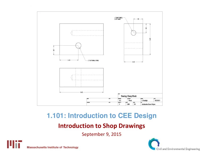
Working (design) sketch Presentation figure Engineering (shop) drawing
Aid in conceptual design Usually hand-drawn Pertinent dimensions
Convey design concepts May be hand drawn or
May be 2-D or 3-D May display key dimensions May display part labels and
Intended to convey all information necessary to
Should include:
One or more views of the part Dimensions Details and notes Drawing and part information
A drawing will contain at least one view of the part Typically two or three views are shown Views are usually 2-D views A 3-D view (usually isometric) may be included for
2-D views are usually orthographic (drawn at right
Orthographic views are most commonly arranged
Help to clarify views of a part Differentiate between part and dimensions
Adds information to a dimension Aids in describing a feature (such as a hole)
The most important aspect of a drawing is clarity Witness lines should extend to features All features require an X and a Y dimension Holes are dimensioned to center Dimensions and details should not reference hidden
Leave gaps between features and witness lines
Software available through IS&T
AutoCAD (Autodesk Suite) SolidWorks
Software available through CEE
KeyCreator