
SLIDE 1
KEK, Tsukuba, March 11, 2009 1
X-ray Calorimeter Arrays for Astrophysics Caroline Kilbourne NASA - - PowerPoint PPT Presentation
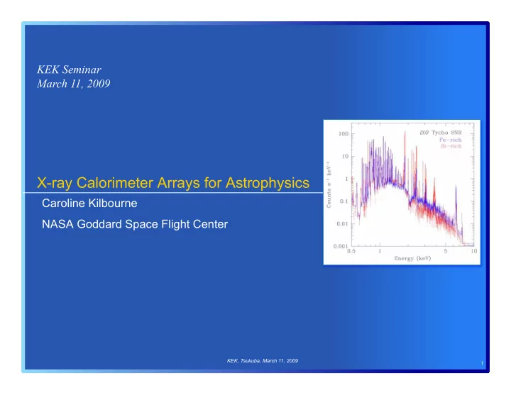
KEK Seminar March 11, 2009 X-ray Calorimeter Arrays for Astrophysics Caroline Kilbourne NASA Goddard Space Flight Center KEK, Tsukuba, March 11, 2009 1 Outline high-resolution astrophysical x-ray spectroscopy
KEK, Tsukuba, March 11, 2009 1
KEK, Tsukuba, March 11, 2009 2
KEK, Tsukuba, March 11, 2009 3
KEK, Tsukuba, March 11, 2009 4
KEK, Tsukuba, March 11, 2009 5
KEK, Tsukuba, March 11, 2009 6
Energy (keV)
Black hole
KEK, Tsukuba, March 11, 2009 7
KEK, Tsukuba, March 11, 2009 8
KEK, Tsukuba, March 11, 2009 9
KEK, Tsukuba, March 11, 2009 10
KEK, Tsukuba, March 11, 2009 11
KEK, Tsukuba, March 11, 2009 12
0.0001 0.001 0.01 0.1 1 10 0.001 0.01 0.1 1 10 100 1000
frequency
KEK, Tsukuba, March 11, 2009 13
10-5 0.0001 0.001 0.01 0.1 1 10 0.001 0.01 0.1 1 10 100 1000
frequency
KEK, Tsukuba, March 11, 2009 14
KEK, Tsukuba, March 11, 2009 15
KEK, Tsukuba, March 11, 2009 16
KEK, Tsukuba, March 11, 2009 17
KEK, Tsukuba, March 11, 2009 18
KEK, Tsukuba, March 11, 2009 19
KEK, Tsukuba, March 11, 2009 20
KEK, Tsukuba, March 11, 2009 21
KEK, Tsukuba, March 11, 2009 22
KEK, Tsukuba, March 11, 2009 23
KEK, Tsukuba, March 11, 2009 24
KEK, Tsukuba, March 11, 2009 25
KEK, Tsukuba, March 11, 2009 26
KEK, Tsukuba, March 11, 2009 27
We made data cuts based on the DC level of the signal channel prior to a pulse, which is representative of the TES temperature just before the x-ray is absorbed. Such a cut removes sensitivity to slight variations in the TES bias point that may be due to any of a number of systems issues. Thus, 1.8 eV should represent the intrinsic resolution of this detector, for which we measured 2.1-eV resolution without the data cuts.
KEK, Tsukuba, March 11, 2009 28
250 µm
KEK, Tsukuba, March 11, 2009 29
KEK, Tsukuba, March 11, 2009 30
KEK, Tsukuba, March 11, 2009 31
KEK, Tsukuba, March 11, 2009 32
view from back through nitride membrane
KEK, Tsukuba, March 11, 2009 33
KEK, Tsukuba, March 11, 2009 34
international MMC collaboration led by S. Bandler (GSFC) includes Brown, Heidelberg, NIST/Boulder and PTB/Berlin
KEK, Tsukuba, March 11, 2009 35
KEK, Tsukuba, March 11, 2009 36
KEK, Tsukuba, March 11, 2009 37
KEK, Tsukuba, March 11, 2009 38
KEK, Tsukuba, March 11, 2009 39
KEK, Tsukuba, March 11, 2009 40
KEK, Tsukuba, March 11, 2009 41
KEK, Tsukuba, March 11, 2009 42
KEK, Tsukuba, March 11, 2009 43
KEK, Tsukuba, March 11, 2009 44
KEK, Tsukuba, March 11, 2009 45