
SLIDE 1
1
Wires
Professor Chris Kim
University of Minnesota
- Dept. of ECE
chriskim@umn.edu www.umn.edu/~chriskim/
2
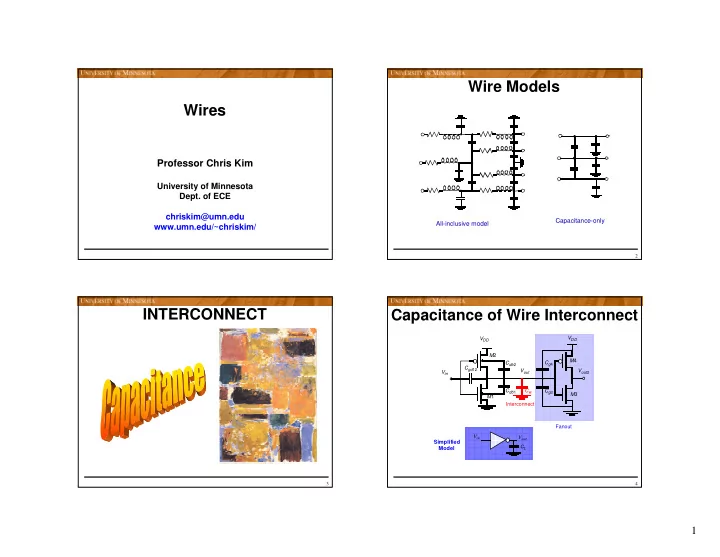
Wire Models
All-inclusive model Capacitance-only
3
INTERCONNECT
4
Capacitance of Wire Interconnect
VDD VDD Vin Vout M1 M2 M3 M4 Cdb2 Cdb1 Cgd12 Cw Cg4 Cg3 Vout2 Fanout Interconnect Vout Vin CL Simplified Model