
Datorteknik F1 bild 1
What is a bus?
■ Slow vehicle that many people ride together – well, true... ■ A bunch of wires...
Datorteknik F1 bild 2
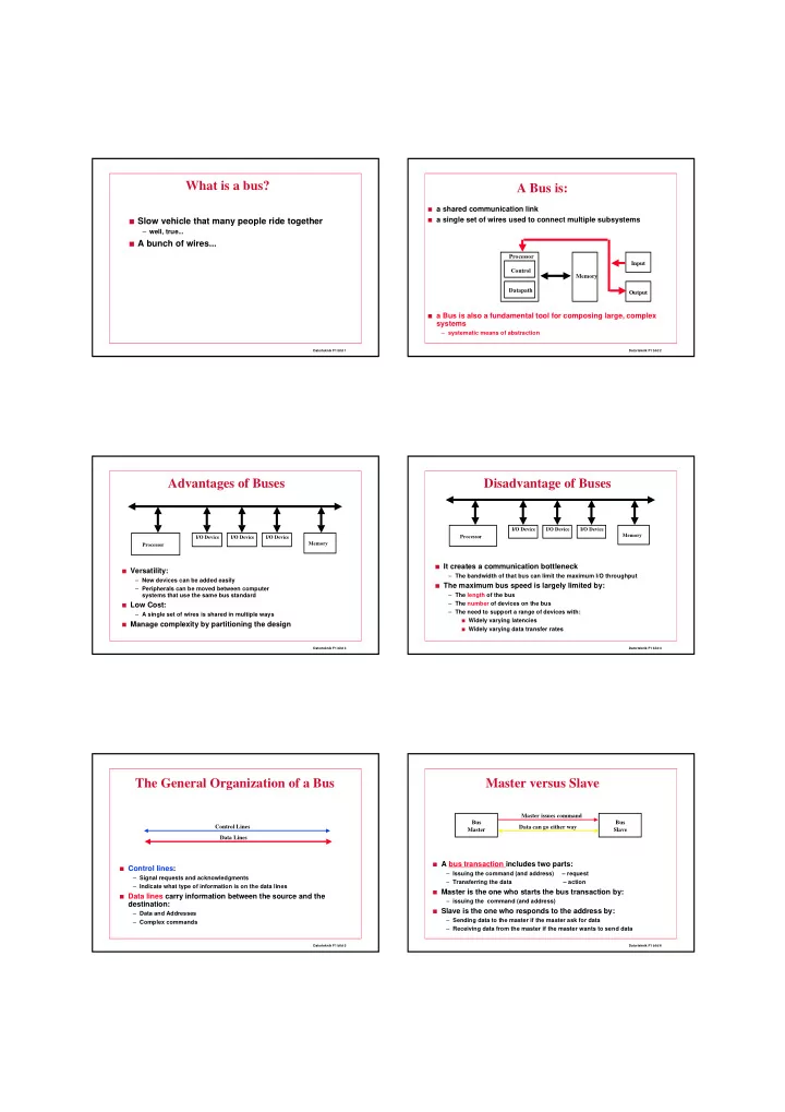
A Bus is:
■ a shared communication link ■ a single set of wires used to connect multiple subsystems ■ a Bus is also a fundamental tool for composing large, complex
systems
– systematic means of abstraction Control Datapath Memory Processor Input Output
Datorteknik F1 bild 3
Advantages of Buses
■ Versatility: – New devices can be added easily – Peripherals can be moved between computer systems that use the same bus standard ■ Low Cost: – A single set of wires is shared in multiple ways ■ Manage complexity by partitioning the design Memory Processor I/O Device I/O Device I/O Device
Datorteknik F1 bild 4
Disadvantage of Buses
■ It creates a communication bottleneck – The bandwidth of that bus can limit the maximum I/O throughput ■ The maximum bus speed is largely limited by: – The length of the bus – The number of devices on the bus – The need to support a range of devices with:
■ Widely varying latencies ■ Widely varying data transfer rates
Memory Processor I/O Device I/O Device I/O Device
Datorteknik F1 bild 5
The General Organization of a Bus
■ Control lines: – Signal requests and acknowledgments – Indicate what type of information is on the data lines ■ Data lines carry information between the source and the
destination:
– Data and Addresses – Complex commands Data Lines Control Lines
Datorteknik F1 bild 6
Master versus Slave
■ A bus transaction includes two parts: – Issuing the command (and address) – request – Transferring the data – action ■ Master is the one who starts the bus transaction by: – issuing the command (and address) ■ Slave is the one who responds to the address by: – Sending data to the master if the master ask for data – Receiving data from the master if the master wants to send data Bus Master Bus Slave Master issues command Data can go either way