Waste Heat Recovery Bigstone Plant Brian Deschner Biography - - PowerPoint PPT Presentation

waste heat recovery bigstone plant brian deschner
SMART_READER_LITE
LIVE PREVIEW

Waste Heat Recovery Bigstone Plant Brian Deschner Biography - - PowerPoint PPT Presentation

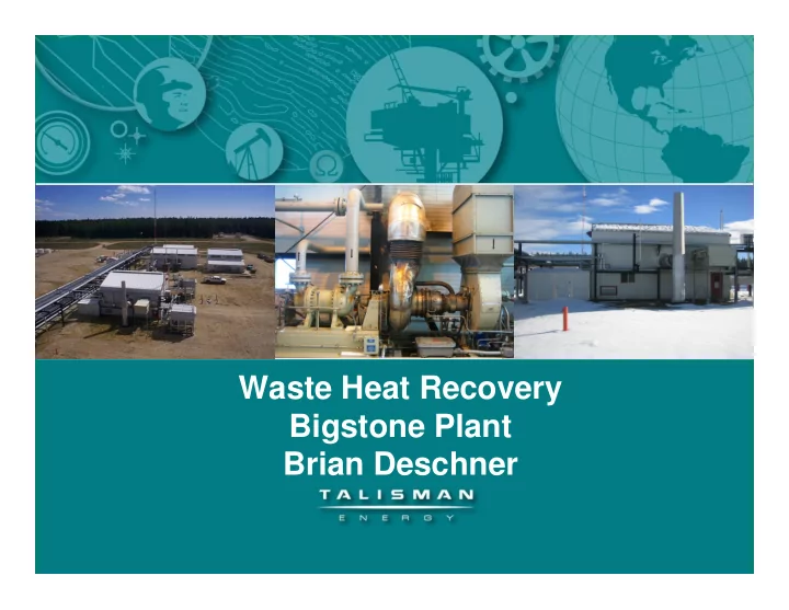
Waste Heat Recovery Bigstone Plant Brian Deschner Biography Employed with Talisman for 25 years Worked 14 years in Chauvin in Oilfield as Engineering Technologist, operated wells and batteries, optimized wells, managed downhole work


slide-1
SLIDE 1

Waste Heat Recovery Bigstone Plant Brian Deschner

slide-2
SLIDE 2

Biography

  • Employed with Talisman for 25 years
  • Worked 14 years in Chauvin in Oilfield as Engineering Technologist,
  • perated wells and batteries, optimized wells, managed downhole

work and supervised service rigs

  • The last 11 years have been focused in Edson area gas properties as

an Operations Technologist

  • Currently working in a role as Rotating Equipment Technologist
  • Certified Engineering Technologist
slide-3
SLIDE 3

Agenda

  • Background – Bigstone Plant
  • WHRU Project Background and Purpose
  • Waste Heat Recovery Unit Design
  • Controls– Instrumentation and Logic
  • Challenges
  • Installation
  • Final Pictures
  • Summary --Benefits / Impacts
  • Moving Forward– Future Considerations
  • Questions
slide-4
SLIDE 4

Background - Bigstone Plant

  • Plant was built in 1995 by Petromet Resources Ltd.
  • Sweet gas plant at 14-28-59-22 W5M
  • Licensed throughput of 80 mmcf/d sales and 85 mmcf/d raw
  • Compression – 4 Reciprocating Inlet and 2 Solar Turbine Sales Compressors
  • Starting looking at WHRU project in 2006, opportunity existed because of the need for

additional heat in the process, installed in 2009

slide-5
SLIDE 5

WHRU Project Background

  • Waste Heat Recovery Unit (WHRU):

– Recovers waste heat from exhaust of sales compressors and use heat exchangers to heat process fluids – Replaces fired heaters in current heat systems Hot Oil (Process) Glycol (Heat tracing) – Fuel gas savings – Increases heat medium reliability Glycol system was taxed

slide-6
SLIDE 6

WHRU Project Background--Turbines

  • Saturn T1600 Solar Turbine Engine

Centrifugal compressor attached

Air Intake Exhaust Pipe Gas Compressor

slide-7
SLIDE 7

WHRU Project Background-- Turbines

  • Outside view of Solar Turbine Building where WHRU was installed
  • Replaced current exhaust stack with a dump stack and the WHRU (built into

a second stack)

  • Replaces fired heaters for hot oil and glycol (7.5 mm BTU/h)
  • Excess heat is diverted up the dump stack
slide-8
SLIDE 8

WHRU Project Background

  • Installation Site:

WHRU replaced existing exhaust stack This stack provided easy access to pipe-rack Existing hot oil heater and glycol heater were kept in line

slide-9
SLIDE 9

WHRU Design- Sales Compressors

  • Engine Performance:

Engine Inlet Temp 10.0 ° C Driven Equipment Speed 22300 RPM Net Output Power 987 kW Heat Rate 15649 kJ/kWh Inlet Air Flow 20994 kg/h Engine Exhaust Flow 20215 kg/h Exhaust Temperature 527 ° C

  • Heat Output

11 mm BTU/h (One Turbine Exhaust)

slide-10
SLIDE 10

WHRU Design-- Hot Oil Heater

  • Design Conditions

Load 6.0 mm BTU/h Inlet Temp 160 ° C Outlet Temp 180 ° C

  • Esso Thermoil-- Heat Transfer Oil 46

Max Temp 200 ° C

  • Fuel Gas Usage

Approx 175 mcf/d (6.0 mm BTU/hr)

  • Heat Usage

Glycol reboiler to regenerate tri-ethylene glycol De-ethanizer bottom and de-ethanizer reboiler to release light ends from condensate

slide-11
SLIDE 11

WHRU Design- Glycol Heater

  • Design Conditions

Load 1.5 mm BTU/h Inlet Temp 40 ° C Outlet Temp 80 ° C

  • 50/50 Ethylene Glycol – Water Mixture
  • Fuel Gas Usage

Approx 125.0 mcf/d (1.5 mm BTU/h)

  • Heat Usage

Building heat (roughneck heaters) Heat Tracing (pipes and tanks)

slide-12
SLIDE 12

WHRU Design – Initial Concept

slide-13
SLIDE 13

WHRU Design – Final Design

slide-14
SLIDE 14

WHRU Design – Final Design

slide-15
SLIDE 15

Controls

  • Heat input into each thermo fluid needed to be controlled due to the extreme difference

in operating temperatures

  • Heat transferred to the hot oil and glycol controlled by exhaust flow through the WHRU

Stack

  • Exhaust flow is controlled by the main diverter for both fluids, glycol also secondarily

controlled by additional damper

  • Both fluids heated so that they reach optimum temperature as they return from the

process

  • Both fluids continue to run through existing fired line heater for additional heating if

needed

  • Both exchangers installed with high temperature protection and low flow protection,

incorporated into the plant shutdown key

  • Fire detection shutdown in stack (would be the result of ruptured tube)
slide-16
SLIDE 16

Challenges

  • Incorporating the 2 fluids with different properties into one WHRU unit,

presented unique control problems. Installed damper on glycol system to provide secondary control

  • Purge time of the WHRU stacks, went from 30 seconds to 5 minutes

Installed new starters to handle the incremental time Tied starters into flare system Installed burst plate in system

  • Control system presented unique challenges

Lots of Hazop meetings to ensure that we provided proper protection Installed many layers of protection

slide-17
SLIDE 17

Installation- Site layout

Main Pipe-Rack Installation Site Hot Oil Heater and Pumps Glycol Heater and Pumps

slide-18
SLIDE 18

Installation- Isometric

slide-19
SLIDE 19

Installation

Took advantage of previous outage to install all hot oil/glycol tie-in

connections Installed WHRU complete with pilings, associated piping, and all instrumentation while Plant was on line Took advantage of scheduled outage to complete the final tie-ins which included : – Removing turbine exhaust stack and installing transition piece to connect WHRU to turbine exhaust – Commissioning of the EI Systems – Installed new Solar Turbine Starters and tied the starter exhaust into the flare system

slide-20
SLIDE 20

WHRU Picture

slide-21
SLIDE 21

WHRU Picture

slide-22
SLIDE 22

Summary – Benefits/Impact

  • Utilization of Solar Turbine Sales Compressor exhaust waste heat to heat

process liquids

  • Replaces existing hot oil and glycol heat mediums, allows 2 line heaters to

be shut in

  • Maintains heat in buildings during winter by maintaining glycol temperature
  • Reduction in fuel gas usage of 0.3 mmscf/day
  • CO2 reduction of 5,900 t/y
  • N2O reduction of 0.10 t/y
  • Capital cost of $875k, payout of 2.0 years based on a fuel gas cost of

$4.00 /mcf

  • Potential of adding twin unit on 2nd Solar Turbine Compressor
  • WHRU minimizes our environmental impact
slide-23
SLIDE 23

Future Considerations

  • Technology can be utilized elsewhere now that it has been proven
  • This design could be added to the 2nd Solar Turbine Compressor at

Bigstone if an application is identified

  • Installation costs can be reduced due to having the upfront

Engineering done– cost could range from $0.5 mm to 1.0 mm depending on application

  • Future Turbine/ Centrigifugal Compressor installs could be justified

based on installing WHRUs

  • Reciprocal Compressor Applications -- Further research needed
slide-24
SLIDE 24

Questions?

Thanks to the following people for their contributions and advice Dave Pillage (Project Supervisor) Yin Yanhua (Coop Student) Liam Russel (Coop Student) John Foxcroft (WP Engineering) Noel Charchuk (Heatech) Doug Kinas (Solar Turbine)