VOID FORMATION IN AN ANISOTROPIC WOVEN FIBER DURING RESIN TRANSFER - - PDF document

void formation in an anisotropic woven fiber during resin
SMART_READER_LITE
LIVE PREVIEW

VOID FORMATION IN AN ANISOTROPIC WOVEN FIBER DURING RESIN TRANSFER - - PDF document

18 TH INTERNATIONAL CONFERENCE ON COMPOSITE MATERIALS VOID FORMATION IN AN ANISOTROPIC WOVEN FIBER DURING RESIN TRANSFER MOLDING Daigo Seto 1* , Ryosuke Matsuzaki 2 , Akira Todoroki 1 , Yoshihiro Mizutani 1 1 Dept. of Mechanical Science and


slide-1
SLIDE 1

18TH INTERNATIONAL CONFERENCE ON COMPOSITE MATERIALS

  • 1. Introduction

RTM (Resin Transfer Molding) is a manufacturing method of fiber reinforced polymer composites, in which a dry fiber is set in molding dies beforehand and is impregnated by resin flow driven by applied pressure before resin curing and solidification. Though the method has high cost performances and high mass productivity, in the process, air bubbles are possibly generated in resin and remain as voids in the product. Since the remained voids result in decrease of the mechanical properties such as inter laminar share strength or bending stiffness [1][2], the reduction method is required to improve performance of the manufacturing process. In the past, various causes of the void generation have been investigated and the one is air entrapped at flow front during impregnation as shown in Fig. 1 because of non-uniform structure of fiber mat [3][4][5]. In this work, the void generation by the air entrapping is focused. The Air entrapping is observed during impregnation

  • f a fiber mat which is composed of fiber bundles

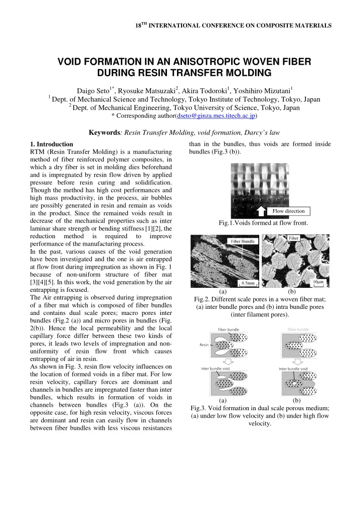
and contains dual scale pores; macro pores inter bundles (Fig.2 (a)) and micro pores in bundles (Fig. 2(b)). Hence the local permeability and the local capillary force differ between these two kinds of pores, it leads two levels of impregnation and non- uniformity of resin flow front which causes entrapping of air in resin. As shown in Fig. 3, resin flow velocity influences on the location of formed voids in a fiber mat. For low resin velocity, capillary forces are dominant and channels in bundles are impregnated faster than inter bundles, which results in formation of voids in channels between bundles (Fig.3 (a)). On the

  • pposite case, for high resin velocity, viscous forces

are dominant and resin can easily flow in channels between fiber bundles with less viscous resistances than in the bundles, thus voids are formed inside bundles (Fig.3 (b)). Fig.1.Voids formed at flow front. (a) (b) Fig.2. Different scale pores in a woven fiber mat; (a) inter bundle pores and (b) intra bundle pores (inter filament pores). (a) (b) Fig.3. Void formation in dual scale porous medium; (a) under low flow velocity and (b) under high flow velocity.

VOID FORMATION IN AN ANISOTROPIC WOVEN FIBER DURING RESIN TRANSFER MOLDING

Daigo Seto1*, Ryosuke Matsuzaki2, Akira Todoroki1, Yoshihiro Mizutani1

1 Dept. of Mechanical Science and Technology, Tokyo Institute of Technology, Tokyo, Japan 2 Dept. of Mechanical Engineering, Tokyo University of Science, Tokyo, Japan

* Corresponding author(dseto@ginza.mes.titech.ac.jp)

Keywords: Resin Transfer Molding, void formation, Darcy’s law

Flow direction

slide-2
SLIDE 2

Fig.4. Dependency of void fraction to resin flow velocity. Fig.5. Anisotropic plane woven fiber (YEM1801). Additionally, past researches [5][6][7] demonstrated that amount of entrapped air (void) depends on macroscopic flow velocity during impregnation and

  • ptimum resin velocity exists for minimization of

void content. Based on the theory, the numerical simulation to predict distribution of void content in a product has developed and the method

  • f
  • ptimization of RTM process by adjusting flow front

velocity to be equal to the optimum value has also presented [8][9]. However, dependency of void fraction on flow velocity differs from the kind of fabric [6] because

  • f difference of structures inside/outside bundles

which affect on resin flow and void formation. Furthermore, in the case of an anisotropic fabric which has different structure in each direction is applied, direction of resin flow against fiber

  • rientation may also affect to void formation. In
  • ther words, in anisotropic fabric, void content may

depend on not only flow velocity but also the direction. In this work, void formation in a plane woven anisotropic fabric is regarded, which contains two different types of fiber bundles in each normal directions; thin bundles (warp) and thick bundles (weft) as shown in Fig. 5. Especially, void generated in spaces between fiber bundles are treated since the void fraction inter bundles tends to be high Fig.6 Void formation in a unit structure of a plane woven fabric. compared to the value of voids generated in spaces in bundles.

  • 2. Model of void formation

In this paper, void generation in plane structure is

  • focused. However, during RTM process, it is also

possible that void are formed in the cross section of multi layers [10]. Structure of a plane woven fabric is simplified into continuity of the unit structures shown in Fig. 6, which consists of two longitudinal bundles, two transverse against macroscopic flow direction. Each bundles are consists of hundreds fibers and capillary forces act strongly on resin flows in pores inside the bundles. When macroscopic resin flow impregnates the structure, resin flow routes can be divided into two;

  • ne which goes through a channel inter bundles and

another which bypasses channel inside bundles. Void is formed in the inter bundles channel in the case that resin go through inside bundles faster than filling the inter bundle channel; Tb<Tc (1) Where Tb is time required to fill intra bundle channels and Tc is that of the inter bundle channel. These impregnation times are derived by Darcy’s law; as (2) and (3)

P K L T ∆ =

c 2 l c c

µφ

(2)

cap cap

P K L P P K L T

b 2 t b b 2 l b b

4 ) ( µφ µφ + + ∆ = (3) Where Kc is permeability in channels between bundles, Kb is the permeability of longitudinal direction in pores inside bundles, µ is viscosity of

slide-3
SLIDE 3

3 VOID FORMATION IN AN ANISOTROPIC WOVEN FIBER DURING RESIN TRANSFER MOLDING

resin, Ll and Lt is distances between bundles as shown in Fig. 6 respectively, Pcap is capillary force acts in pores inside bundles, and ∆P is applied pressure difference over the unit structure. φc is porosity of fiber mat and φb is porosity inside bundles. Void content is considered to be ratio of channel between bundles which have not filled by resin bypasses inside bundles;

( ) c

c b

1 φ T T Vf − = (4) Finally, the void content can be described as a function of velocity of the macroscopic resin flow. In the case that this analysis model is applied to anisotropic fiber mat, the parameters such as L or K defers in each direction of impregnation against fiber

  • rientation and the function of the void content also

depends on the direction. It means that the

relationship between the void content and the impregnation velocity differs in each impregnation directions; warp direction and weft direction. The predicted relationship by this model is shown later in chapter tree.

  • 3. Experiments for validation

For validation of the influence of the direction of impregnation on void fraction, 1D flow RTM experiment and measurement of the void content in manufactured specimens are conducted. 3.1 Manufacturing of specimen

  • Fig. 7 shows the experimental set up of 1D flow

RTM conducted to manufacture specimens for detection of relationships between impregnation velocity and void content. Rectangular glass fiber (200×50mm×1ply) is set between two plate dies and each long side is sealed by sealing tape. Distance between two plates is kept to be constant by clamping plate spacers placed

  • utside of the sealing tape. Each open ends of the set

up are connected individually to resin bucket and resin trap which is connected to vacuum pump

  • further. As resin is injected by applying constant

vacuum pressure and flows only in the longitudinal direction from one side to another, flow direction against fiber orientation is unchanged through impregnation of the all length. Upper plate is made

  • f transparent acryl and the progress of the flow

Fig.7. Experimental setup. Fig.8. Image analysis for measurement of void fraction. front is recorded by a video camera set over the

  • assembly. After resin curing, manufactured plate is

released from the dies. The experiment is conducted for each normal direction of anisotropic woven fabric; warp bundle direction and weft bundle direction. In the experiments, glass fiber YEM1801 (Solar) is used as the fabric and UP resin Sundhoma PC184-C (DH Material) is used as the resin. Table 1 shows the various values of the materials used in the experiment. 3.2 Measurement of void content Void contents in each areas of the molded plate are measured by image analysis. Images of voids in the specimens are taken by microscope and analyzed by the software Vision Assistant 8.5 (National Instruments) to measure ratio of voids in a certain

  • area. Examples of images before/after the process

are shown in Fig. 8. 3.3 Results The results of flow front progress in warp directional flow recorded during the experiment are shown in

  • Fig. 9. The flow front position x against the saturated

time t is expressed as (5) by Darcy’s law;

µφ Pt K x ∆ = 2

(5)

slide-4
SLIDE 4

Then impregnation velocity U at each position x can also be obtained by derivation of the curve in Fig. 9. The results of measured void content versus the distance from inlet in warp directional flow are shown in Fig. 10. The void content increases as the distance increases since the impregnation velocity decreases and capillary force becomes dominant.

  • Fig. 11 shows the relationship between impregnation

velocities and void content obtained from the experiment, with the prediction by the analysis model explained in chapter two. Difference is

  • bserved between each impregnation direction and

similarity of the tendency can be seen between the experimental results and the model. However, some difference also can be observed between them and it is considered to result from effect of void motion after formation which is not included in the analysis model in this study.

  • 4. Conclusion

By analysis model of void formation in a channel between fiber bundles in plane woven fabric, it was shown that, when anisotropic fiber mat is applied, amount of voids formed at flow front depends not only on velocity of impregnation but also on the direction against fiber orientation. The prediction was also examined by experimentally and good agreement was obtained between them.

Table 1 List of material values Variable Value Kc,warp [m2] 1.1×10⁻¹⁰ Kc,weft [m2] 5.0×10⁻¹¹ Kb [m2] 5.8×10⁻¹² φc 0.25 φt 0.58 lwarp [m] 6×10⁻⁴ lweft [m] 9×10⁻⁴ Pcap [kPa] 16.6 µ [Pa s] 0.169

  • Fig. 9. Flow front progress in warp direction during

the experiments.

  • Fig. 10. Void content versus distance from inlet in

warp direction. Fig, 11. Void content versus impregnation velocity. References

[1] J. Varna, R. Joffe, L.A. Berglund and T.S. Lundström “Effect of voids on failure mechanisms in RTM laminates” Composites Science and Technology Vol. 53, pp 241-249, 1995 [2] S.R. Ghiorse “Effect of void content on the mechanical properties of carbon/epoxy laminates” SAMPE Quarterly Vol. 24, No. 2, pp 54-59, 1993

slide-5
SLIDE 5

5 VOID FORMATION IN AN ANISOTROPIC WOVEN FIBER DURING RESIN TRANSFER MOLDING [3] N. Patel and L.J. Lee “Effects of fiber mat architecture on void formation and removal in liquid composite molding” Polymer Composite Vol. 16, No. 5, pp 386–99, 1995 [4] C. Binetruy, B. Hilaire and J. Pabiot “Tow Impregnation Model and Void Formation Mechanisms during RTM” Journal of Composite Materials Vol. 2, No. 3, pp 223-245, 1998 [5] N. Patel and L.J. Lee “Modeling of Void Formation and Removal in Liquid Composite Molding” Polymer Composites, Vol. 17, No. 1, pp 96-114, 1996 [6] J. Sebastien and E. Ruiz “Porosity reduction using

  • ptimized flow velocity in Resin Transfer Molding”

Composites Part A Vol. 39, No. 12, pp 1859-1868, 2008 [7] J.S.U. Shell, M. Deleglise, C. Binetruy, P. Krawczak, and P. Ermanni “Numerical prediction and experimental characterization of meso-scale-voids in liquid composite moulding”. Composites Part A Vol. 38, pp 2460-2470, 2007. [8] E. Ruiz, V. Achim, S. Soukane, F. Trochu and J. Bréard “Optimization of injection flow rate to minimize micro/macro-voids formation in resin transfer molded composites” Composites Science and Technology Vol. 66, No. 3-4, pp 475-486, 2006 [9] D.H. Lee and W.I. Lee “Analysis and minimization

  • f void formation during resin transfer molding

process” Composites Science and Technology Vol. 66,

  • No. 16, pp 3281–3289, 2006

[10] J. Hu, Y. Liu and X. Shao “Study on void formation in multilayer woven fabrics“ Composites Part A Vol. 35, No. pp 595-603, 2004