VOICE OVER CIRCUIT SWITCHING www.sorin-schwartz.com NETWORKS PHASE - - PowerPoint PPT Presentation

voice over circuit switching
SMART_READER_LITE
LIVE PREVIEW

VOICE OVER CIRCUIT SWITCHING www.sorin-schwartz.com NETWORKS PHASE - - PowerPoint PPT Presentation

VoIP Technologies by Sorin M. SCHWARTZ VOICE OVER CIRCUIT SWITCHING www.sorin-schwartz.com NETWORKS PHASE TWO - ANALOG TELEPHONE, DIGITAL EXCHANGE - Signals - User to exchange: analog voice - Exchange to exchange: digitized voice -


slide-1
SLIDE 1

VoIP Technologies

by Sorin M. SCHWARTZ www.sorin-schwartz.com

VoIP 03 1

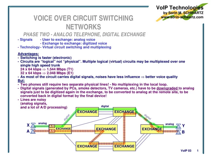
VOICE OVER CIRCUIT SWITCHING NETWORKS

PHASE TWO - ANALOG TELEPHONE, DIGITAL EXCHANGE

EXCHANGE analog analog

Y

digital

A X

EXCHANGE EXCHANGE

B

EXCHANGE EXCHANGE EXCHANGE

A/D A/D

EXCHANGE Advantages:

  • Switching is faster (electronic)
  • Circuits are “logical” not “physical”. Multiple logical (virtual) circuits may be multiplexed over one

single high speed trunk 24 x 64 kbps ⇒ 1.544 Mbps (T1) 32 x 64 kbps ⇒ 2.048 Mbps (E1)

  • As most of the circuit carries digital signals, noises have less influence ⇒ better voice quality

But:

  • Two phones still require two separate physical lines! - No multiplexing in the local loop.
  • Digital signals (generated by PCs, smoke detectors, TV cameras, etc.) have to be downgraded to analog

signals just to be digitized again in the exchange, to be converted to analog at the remote site, to be converted back in digital format by the final device!

  • Lines are noisy

(analog signals, and a lot of A/D processing)

  • Signals
  • User to exchange: analog voice
  • Exchange to exchange: digitized voice
  • Technology- Virtual circuit switching and multiplexing
slide-2
SLIDE 2

VoIP Technologies

by Sorin M. SCHWARTZ www.sorin-schwartz.com

VoIP 03 2

VoIP CALL FLOW

VoIP DEVICE to VoIP DEVICE

In different zones

  • T1 to T3
  • GK B finds “tel-(B)T3” in

its table and sends to GK A, “IP-T3”

  • GK A sends to T1,

“IP-T3”

  • T1 generates VoIP

packets with IP DA = IP-T3

Phone number IP address tel-(A)T1 IP-T1 tel-(972)…(e.g.B) IP-GW A1 tel-(A)…(e.g.A) IP-GW A2 tel-(86)…(e.g.C) Zone B; IP-GK B tel-(A)T2 IP-T2

GK A Table

tel-(B)…(e.g.D,T3,4) Zone B; IP-GK B Phone number IP address tel-(B)T3 IP-T3 tel-(972)…(e.g.B) Zone A; IP-GK A tel-(B)…(e.g.D) IP-GW B2 tel-(86)…(e.g.C) IP-GW B1 tel-(B)T4 IP-T4

GK B Table

tel-(A)…(e.g.A,T1,2) Zone A; IP-GK A

Long distance PSTN R R R R R R R Internet / intranet

Local PSTN-A Local PSTN-B

Terminal T1 Terminal T2 Multipoint Control Unit (MCU A) System Controller (Gatekeeper) (GK A) Media Gateway (GW A1) GW A2 Router A Terminal T3 Terminal T4 Multipoint Control Unit (MCU B) System Controller (Gatekeeper) (GK B) Media Gateway (GW B1) GW B2 Router B PABX A PABX B

B A C zone A zone B D

slide-3
SLIDE 3

VoIP Technologies

by Sorin M. SCHWARTZ www.sorin-schwartz.com

VoIP 03 3

VoIP SYSTEM ARCHITECTURE

ITU-T H.323

Summary

Router A GK A GK B MCU MP MC IP net Router B PSTN

GW A2 terminal

GW A1 GW B1

terminal

ITU-T H.323 Architecture

Router A Syst. Contr. A Syst. Contr. B MCU MP MC MGC A1 SG A1 MG A1 IP net Router B PSTN MG B1 MGC B1 SG B1

C S

SG MGC MG

C S

SG MGC MG

C S

SG MGC MG

C S C S

H.323 basic call flow

1.- End points register with the zone GK 2.- Terminal / GW query GK for IP address to be used for controls 3.- GK may indicate as the entity to send controls to:

  • itself (GK routed call), or
  • the remote end (direct routed call)
  • If GK has no relevant information, it may contact other servers (local or in the Internet)

4.- Terminal / GW query the entity indicated by GK in step 3, for the IP address to be used to send media

slide-4
SLIDE 4

VoIP Technologies

by Sorin M. SCHWARTZ www.sorin-schwartz.com

VoIP 03 4

VoIP SYSTEM ARCHITECTURE

SIP (Session Initiation Protocol)

Router A SIP PROXY server (A) MCU MP MC IP net Router B SG MGC MG SG MGC MG SG MGC MG PSTN UA

UAC UAS

UA

UAC UAS

UA

UAC UAS

SG MGC MG UA

UAC UAS

SG MGC MG UA

UAC UAS

SIP Architecture

SIP REDIRECT server SIP PROXY server (B) LOCATION server SIP REGISTRAR server Router A Syst. Contr. A Syst. Contr. B MCU MP MC MGC A1 SG A1 MG A1 IP net Router B PSTN MG B1 MGC B1 SG B1

C S

SG MGC MG

C S

SG MGC MG

C S

SG MGC MG

C S C S

SIP basic call flow

1.- User Agents register with the Registrar server (Registrar server maintains user’s whereabouts in a Location Server 2.- User Agent Client query SIP server for IP address to be used for controls 3.a.- Proxy server indicates itself as entity to send controls to. It forwards client’s requests to the called party or to a better informed server (it acts on client’s behalf). It executes call signaling on behalf of the party it serves (retaining billing information). 3.b.- Redirect server responds to client’s request by providing to it the coordinates of the called party or those of another server, better informed about called party location. Client has to contact directly the new server. 3.c.- Last server has to indicate the coordinates of the called party (for media)

slide-5
SLIDE 5

VoIP Technologies

by Sorin M. SCHWARTZ www.sorin-schwartz.com

VoIP 03 5

VoIP SYSTEM ARCHITECTURE

Gateway Decomposition

“GW Decomposition” Architecture

Router A Syst. Contr. Syst. Contr. B IP net Router B MG B1 MGC B1 SG B1

C S

SG MGC MG

C S

SG MG SG MG

C

SG MG MGC MG Control

S

MG Control PSTN behaves as one H.323 or SIP end point H.323 or SIP MG Control Router A Syst. Contr. A Syst. Contr. B MCU MP MC MGC A1 SG A1 MG A1 IP net Router B PSTN MG B1 MGC B1 SG B1

C S

SG MGC MG

C S

SG MGC MG

C S

SG MGC MG

C S C S

  • The GW is decomposed into its basic elements:
  • one Media Gateway Controller (MGC)(a.k.a

Agent, Call Agent)

  • multiple Media Gateways (MG)
  • MG reports to MGC every event (incoming call,
  • ff hook, hang up, etc.).
  • In response, MGC instructs MG what has to be

done (ring the phone, bring dialed numbers, etc.).

  • MG is simple (cheap)
  • Future services are transparent to MG. Changes affect
  • nly MGC, which will generate new sets of commands

to MG, in order to provide the new services

  • For the external world, MGC together with all its MGs

looks like a node with multiple connections

  • MGs are unaware that the call is established by MGC

using H.323 or SIP.

  • Only MGC understands both MGCP and SIP or H.323
slide-6
SLIDE 6

VoIP Technologies

by Sorin M. SCHWARTZ www.sorin-schwartz.com

VoIP 03 6

VoIP STANDARDS

MAIN STANDARDS

GK A GK B MCU Router A IP net Router B PSTN

GW A2 terminal

GW A1 GW B1

terminal

H.323 GW Decomposition

Router A Syst. Contr. IP net SG MG SG MG

C

SG MG MGC

S

PSTN behaves as one H.323 or SIP end point H.323 or SIP MG Control MG Control MG Control Router A SIP PROXY server (A) IP net Router B PSTN UA

UAC UAS

UA

UAC UAS

UA

UAC UAS

UA

UAC UAS

UA

UAC UAS

SIP REDIRECT server

SIP PROXY server (B) location server

SIP REGISTRAR server

SIP

Restrictions

  • n H.323 usage:

DTS 2001

  • PC to phone

DTS 2002

  • phone to PC

DTS 2003

  • phone to phone

DTS 2004

  • PC to PC

ETSI (TIPHON) not defined RAS H.245 ITU-T SG16 (H.323 suite) H.225.0 (Q 931)

  • Internal to GW
  • H.248 (defined with IETF

MEGACO)

  • MGCP

(-) (-) Telcordia (Bellcore) (-) (-) MGCP Capabilities exchange Field Call signaling System controller to servers Media GW Controller (MGC) to Media GW (MG) Registration Hand shaking processes SIP IETF (SIP suite) SIP not defined

  • MEGACO (defined with

ITU-T SG16 H.248)

  • MGCP

SIP (SDP)