
SLIDE 1
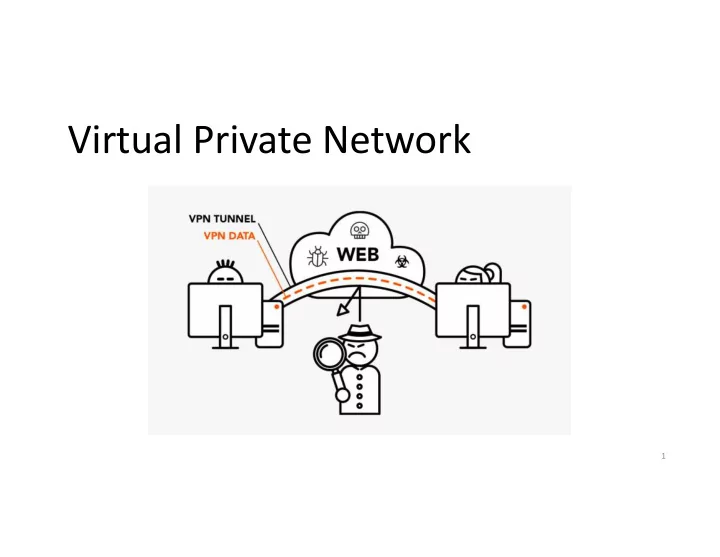
Virtual Private Network
1
Virtual Private Network 1 Introduction Private network - - - PowerPoint PPT Presentation
Virtual Private Network 1 Introduction Private network - physically disconnected from the outside Internet Users Authenticated Still vulnerable if the internal resources use IP address as the basis for authentication Content
1
– Still vulnerable if the internal resources use IP address as the basis for authentication
– Communication within the private network cannot be sniffed from outside.
– Nobody from outside the network can spoof.
surface will significantly broaden.
2
VPN allows users to create a secure, private network over a public network, such as the Internet.
a private network via authentication.
protected via firewalls or reserved IP addresses.
Internet Firewall VPN Server Client
3
This is a typical VPN setup where the “Client” machine wants to connect with machine “V” on a private network. “Client” uses the “VPN Server” to get authenticated to the private network
IP Tunneling
4
9
Firewall VPN Client IP Packet IP Packet
IP head
Encrypted packet Encrypted packet
IP head
for the destination for the VPN server Destination to VPN Server Encrypted packet
IP head
IP Packet
IP head
decrypt Forward to destination
5
– It uses IPSec protocol which operates at the IP layer and has a tunneling mode. – The entire IP packet is encapsulated into a new IP packet with a new header added. – Done at the kernel level
6
– It uses TLS library at the application layer to achieve tunneling. – The entire IP packet is encapsulated into a new TCP/UDP packet with a new header added. – Done at the application level
7
This is just a normal TCP or UDP based SSL connection Satellite Site
8
Primary Site
9
password authentication
10
Any packet to 10.0.8.x will be routed to the VPN client Any packet to 10.0.7.x will be routed to the VPN server
11
packet and directed to the VPN server
Promiscuous mode, Raw packets, filtering
– Physical: Corresponds to the physical Network Interface Card (NIC) – Virtual: A virtualized representation of computer network interfaces that may or may not correspond directly to the NIC card. Example: loopback device
– Work at OSI layer 3 or IP level – Sending any packet to TUN will result in the packet being delivered to user space program
– Work at OSI layer 2 or Ethernet level – Used for providing virtual network adapters for multiple guest machines connecting to a physical device of the host machine
12
application get an IP packet?
– Typically, applications interact with kernel using socket – Using socket, kernel
applications – Applications need to use a different way to interact with kernel
Socket Interface
13
The flag IFF_TUN specifies that we are creating a TUN interface
14
Register a TUN device with the kernel
15
Routing packets to the tunnel
16
Packets to this destination should be routed to the tun0 interface, i.e., they should go through the tunnel. All other traffic will be routed to this interface, i.e., they will not go through the tunnel
17
We did an experiment by sending a ping packet to 10.0.8.32. The packet was sent to the TUN interface and then to our program. We use “xxd” to read from the interface and convert the into hexdump.
0a00 0820: Destination IP (10.0.8.32) 0a00 0863: Source IP (10.0.8.99) IP Header
18
called “hexfile” and run “xxd –r hexfile > packetfile”.
19
– The payloads inside are IP packets – That is why it is called IP tunnel
20
Sending a packet via the tunnel
the tunnel
Receiving a packet from the tunnel
21
two interfaces: socket and TUN
these two interfaces
22
select() will be blocked until one of the interfaces has data.
23
Note: the encryption step is omitted from the code (for the sake of simplicity)
24
Note: the decryption step is omitted from the code (for the sake of simplicity)
25
26
the server program.
– We use 10.4.2.0/24 as IP prefix for the TUN interface (for both VPN Client and VPN Server)
tun0, bring it up and then add a corresponding route to routing table.
27
the client program.
routed to the tun0 interface.
28
via the same VPN tunnel, so that they are protected.
toward the tunnel.
29
the following result:
(192.168.0.6).
30
31
10.0.20.100
Internet
Telnet Program TCP Port VPN Program (Point A) tun0 UDP Port Kernel IP TCP Data Routing IP TCP Data eth1 IP TCP Data Encrypt
New IP
UDP IP TCP Data
New IP
UDP IP TCP Data VPN Program (Point B) IP TCP Data IP TCP Data Decrypt eth1 UDP Port tun0 IP TCP Data Telnet 10.0.20.100 Routing Kernel NIC Card
` `
10.0.20.101 eth2 IP: 10.0.4.1 => 10.0.20.100 New IP: 209.164.131.32 => 128.230.208.97
10.0.4.1 10.0.5.1 209.164.131.32 128.230.208.97
How packets flow from client to server when running “telnet 10.0.20.100” using a VPN
NIC Card NIC Card Data
(a) An Example of packet flow from telnet client to server in Host-to-Gateway Tunnel
32
10.0.20.100
Internet
Telnet Program TCP Port VPN Program (Point A) tun0 UDP Port Kernel IP TCP Data IP TCP Data eth1 IP TCP Data Decrypt
New IP
UDP IP TCP Data
New IP
UDP IP TCP Data VPN Program (Point B) IP TCP Data IP TCP Data Encrypt eth1 UDP Port tun0 IP TCP Data Telnet 10.0.20.100 Kernel NIC Card
` `
10.0.20.101 eth2 IP: 10.0.20.100 => 10.0.4.1 New IP: 128.230.208.97 => 209.164.131.32
10.0.4.1 10.0.5.1 209.164.131.32 128.230.208.97
Routing Data
How packets return from server to client when running “telnet 10.0.20.100” using a VPN
NIC Card NIC Card
(b) An Example of packet flow from telnet server to client in Host-to-Gateway Tunnel
33
34
35
by running the following command (this IP address can change):
dig www.facebook.com
36
Facebook becomes unreachable
One of the IP prefixes belong to Facebook
37
all Facebook traffic. Instead of going through eth6, we use the TUN interface:
the VPN server, so it does not get blocked.
forward it back to us via the tunnel.
38
– TUN/TAP interface
39