SLIDE 1 L1 L2 L L L L L
Various Single Feed CP MSAs
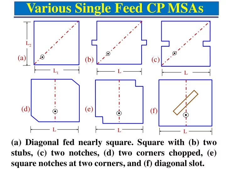
(a) Diagonal fed nearly square. Square with (b) two stubs, (c) two notches, (d) two corners chopped, (e) square notches at two corners, and (f) diagonal slot.
(e) (d) (a) (b) (c) (f)
SLIDE 2 L1 L2
Input impedance, VSWR and AR plots for three values of L2: ( - - - ) 2.9, ( —— ) 2.92, and ( – - – ) 2.95 cm - LHCP
Diagonal Fed Nearly Square MSA
L1 = 3cm, Feed position = (0.15 L1, 0.15 L2) r = 2.55, h = 0.159cm and tanδ = 0.001
SLIDE 3
Nearly square ring MSA with (a) coaxial feed and (b) quarter-wave transformer.
Nearly Square Ring MSA
SLIDE 4
Variations of CMSAs and ETMSAs
(a) Elliptical MSA and CMSA with (b) two notches, (c) two stubs, and (d) a rectangular slot in the centre. (a) Nearly ETMSA, (b) tip-truncated ETMSA, (c)ETMSA with a rectangular slot, and (d) ETMSA with a notch.
SLIDE 5
Compact CP Square MSA with Slits
(a)SMSA with two pairs of unequal slits and (b)SMSA with corners chopped and four bent slits
(a) (b)
Application – GPS (1575 + 10 MHz) antenna, RHCP
SLIDE 6 Compact CMSA with (a) cross slot and (b) curved slot with tuning
- stub. Annular ring MSA with (c) an internal offset polarizer and
slits in the (d) outer and (e) inner circles
Compact CP CMSA with Slits
(a) (b) (c) (d) (e)
SLIDE 7
Gap-Coupled Broadband CP MSA
(a) Three gap-coupled and (b) five gap-coupled square patches with orthogonal feeds for CP
(a) (b)
SLIDE 8
Stacked Broadband CP SMSA
(a) Top and (b) side views of two stacked square patches (a) (b)
SLIDE 9
(a) Square patch with two orthogonal cross slots of unequal lengths and (b) its measured input impedance plot.
(a) (b)
Aperture- Coupled Broadband CP MSA
SLIDE 10
CP Array using Linearly Polarized Elements
Two linearly polarized rectangular patches with 90° rotation and phase difference of 0°, 90°, 180°, and 270°
SLIDE 11
2-Elements Sequentially Rotated Array using CP MSAs (a) Sequentially rotated array of two CP circular elements and (b) superimposed CP response of the two elements
(a) (b)
SLIDE 12
4-Elements Sequentially Rotated Array using CP MSAs Sequential array of four CP elements with 90° rotation and phase difference of 0°, 90°, 180°, and 270°.
SLIDE 13
Measured VSWR and AR plots ( - - - ) conventional and ( —— ) sequentially rotated.
CP Array using CP Elements – VSWR and AR
2 × 4 arrays of circular patches with two notches: conventional and sequentially rotated.
SLIDE 14 Microstrip Antenna Arrays
Electrical Engineering Department, IIT Bombay
gkumar@ee.iitb.ac.in (022) 2576 7436
SLIDE 15 MSA Array Feed Networks
Advantages :
- Reduced feed length
- Reduced losses
- Lower Sidelobe
Disadvantages:
- Beam tilt with Frequency
- Narrow BW
Advantages:
- Equal power to all element
- Larger BW
- Modular in nature
Disadvantages:
- Higher Feed losses
- Higher cross polar
- Series Feed
- Corporate (Parallel) Feed
- Series and Corporate Feed
Series Feed Corporate Feed
SLIDE 16 Series Fed MSA Array
Antenna at Ka-Band
RT 5880 substrate: εr = 2.2, h = 0.254mm and tanδ = 0.0015 Elements Value (mm) Patch Length (pl) 2.68 Patch Width (pw) 3.2 Connecting line length (cl) 2.77 Connecting line width (cw) 0.4 Space between patches 5.45
Patch λ/2 connecting line
SLIDE 17 17
|S11| Plot Input Impedance Plot Radiation Pattern at 36GHz Gain vs Frequency plot
BW for |S11| -10dB-35.9 to 38 GHz (5.6%)
23×1 Series Fed Array at Ka Band
Gain: 19dB at 36 GHz
SLIDE 18
13x1 Series Fed MSA Array at 5.8 GHz
BW for VSWR < 2 is 5.78 to 5.94 GHz Max Gain at 5.82 GHz is ≈17 dB Radiation Pattern at 5.8GHz Patch Length = 16.84mm Patch width = 12.7mm Feed line length = 18.85mm Inter element spacing = 0.6λo
SLIDE 19
Fabricated 7-element series-fed Array
7x1 Series Fed MSA Array at 5.8 GHz
VSWR vs. Frequency Plot Gain vs. Frequency Plot
SLIDE 20
( Central Feed, End Feed ) VSWR vs. frequency Gain vs. frequency plot
Comparison of Central feed with End feed MSAA
SLIDE 21 (a) (b) (c) Radiation Pattern at (a) 5.73, (b) 5.78 and (c) 5.83 GHz
Parameters Central Feed End Feed 1 VSWR <2 Bandwidth (MHz) 100 141 2 Maximum Gain (dBi) 14.8 14.5 3 E-plane HPBW at 5.73 GHz (degrees)
4 E-plane HPBW at 5.78 GHz (degrees)
5 E-plane HPBW at 5.83 GHz (degrees)
0.7 to 12.7 6 Cross-polar levels (dB) 35 20
Comparison of Central feed with End feed (Cont.)
SLIDE 22
Corporate Feed Planar MSA Array at X-Band
X-band antenna designed at f = 8.75 GHz Substrate: RT Duroid 5880 (εr = 2.2, h = 1.59 mm and tanδ = 0.001) Patch Length = 13.23 mm, Patch Width = 10.17 mm Inter element spacing in the E and H planes = 23 mm (0.67λ0) Input Impedance Plot
SLIDE 23
BW for VSWR ≤ 2 is more than 500 MHz Radiation Pattern at 8.75 GHz
Corporate Feed 2x2 MSA Array Results
SLIDE 24
8x8 Corporate feed MSA Array