
SLIDE 1
Digital Systems Basic Circuit Theory Review IV CMPE 650 1 (4/7/03)
UMBC
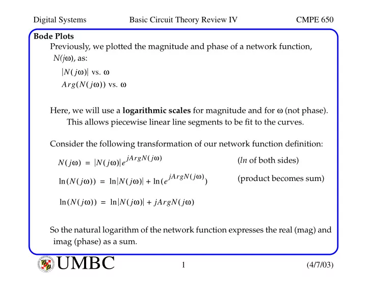
U M B C U N I V E R S I T Y O F M A R Y L A N D B A L T I M O R E C O U N T Y 1 9 6 6Bode Plots Previously, we plotted the magnitude and phase of a network function, N(jω), as: Here, we will use a logarithmic scales for magnitude and for ω (not phase). This allows piecewise linear line segments to be fit to the curves. Consider the following transformation of our network function definition: So the natural logarithm of the network function expresses the real (mag) and imag (phase) as a sum. N jω ( ) vs. ω Arg N jω ( ) ( ) vs. ω N jω ( ) N jω ( ) e jArgN jω
( )
= N jω ( ) ( ) ln N jω ( ) e jArgN jω
( )
( ) ln + ln = (ln of both sides) (product becomes sum) N jω ( ) ( ) ln N jω ( ) jArgN jω ( ) + ln =