
SLIDE 1
Plasma Diagnostics
1
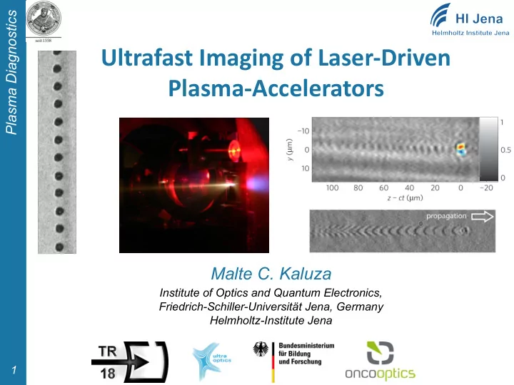
Ultrafast Imaging of Laser-Driven Plasma-Accelerators
Malte C. Kaluza
Institute of Optics and Quantum Electronics, Friedrich-Schiller-Universität Jena, Germany Helmholtz-Institute Jena
Ultrafast Imaging of Laser-Driven Plasma-Accelerators Malte C. - - PowerPoint PPT Presentation
Plasma Diagnostics Ultrafast Imaging of Laser-Driven Plasma-Accelerators Malte C. Kaluza Institute of Optics and Quantum Electronics, Friedrich-Schiller-Universitt Jena, Germany Helmholtz-Institute Jena 1 Outline Plasma Diagnostics
1
Institute of Optics and Quantum Electronics, Friedrich-Schiller-Universität Jena, Germany Helmholtz-Institute Jena
2
3
4
5
6
www.wikipedia.de
7
8
9
H.-P. Schlenvoigt, PhD thesis, Uni Jena (2009)
10
11
earlier later
12
Image courtesy of A.G.R. Thomas
13
$%& '(
14
15
16
17
probe probe cr e e rot
probe