
SLIDE 1
1
UI
EE529 Lecture 30
Static Transfer Switch
Switching model Measurements and Control Examples References: Look at Panel Session Archive
and Custom Power Technology Development
Distribution Series Compensation
Spring 2017
1
list at:
» http://grouper.ieee.org/groups/1409/ » IEEE/PES Distribution Custom Power Task Force
UI
EE529 Lecture 30
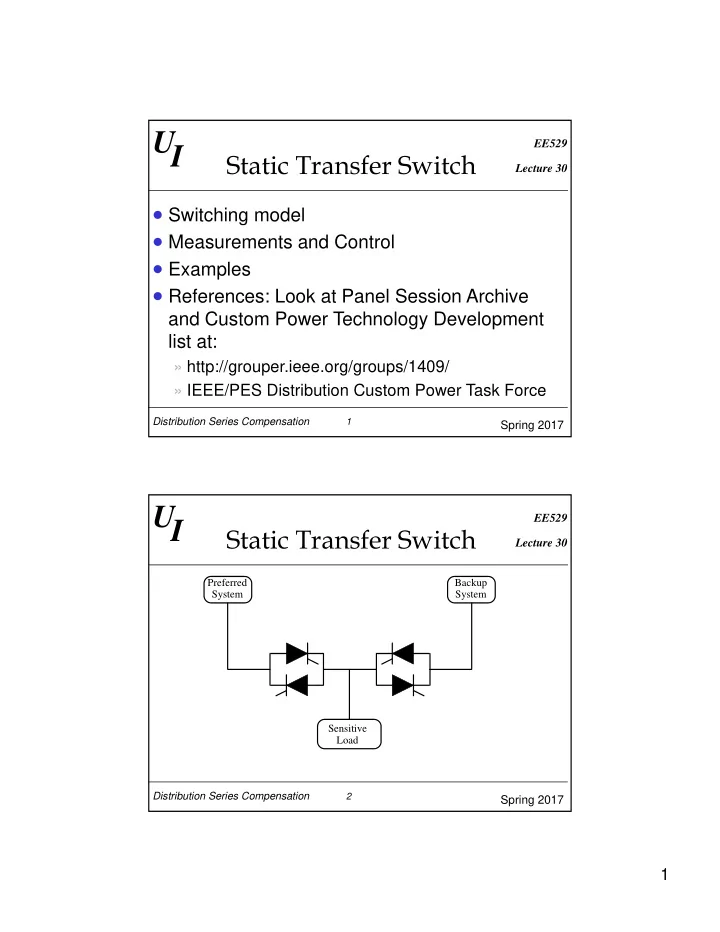
Static Transfer Switch
Preferred System Backup System Distribution Series Compensation
Spring 2017
2
Sensitive Load