
SLIDE 1
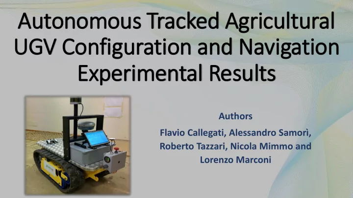
Autonomous Tracked Agricultural UGV Configuration and Navigation Experimental Results
Authors Flavio Callegati, Alessandro Samorì, Roberto Tazzari, Nicola Mimmo and Lorenzo Marconi
UGV Configuration and Navigation Experimental Results Authors - - PowerPoint PPT Presentation
Autonomous Tracked Agricultural UGV Configuration and Navigation Experimental Results Authors Flavio Callegati, Alessandro Samor, Roberto Tazzari, Nicola Mimmo and Lorenzo Marconi Precis isio ion Agric iculture Manual workers and
Authors Flavio Callegati, Alessandro Samorì, Roberto Tazzari, Nicola Mimmo and Lorenzo Marconi
Structure
Architecture
Purposes
Manual workers and Mobile Robots Co-operation
Structure
Architecture
Purposes
Autonomous Navigation Perform Farm Tasks Local Positioning Robustness to Uneven Ground
To achieve Robustness:
To obtain Local Positioning:
Experimental Tests to evaluate performances
Structure
Architecture
Purposes
Mechanical Structure Sensor Suite
Tracked Vehicle
PROs
CONs
3D Laser Scanner
Inertial Measurement Unit
GPS Receiver
Structure
Architecture
Purposes
Rover management and control
Two basic software elements
Running on the onboard computer
HMI CONTROL SYSTEM
System State Mission/ Commands
Structure
Architecture
Purposes
Bidirectional UDP communication with the Control system
Functions
Appearence
Structure
Architecture
Purposes
Pose estimation (PE)
Implemented in ROS (Robot Operating System)
Row State Machine (RSM)
Row control
HMI
HMI Control system Pose Estimation Row State Machine
System State Mission/ Commands
DRIVERS
Speed Ref.
Motors/ Sensors Row Control
Sensors
Structure
Architecture
Purposes
Kinematic model (Differential Drive)
Estimation of the lines of trees
𝒘: translation velocity
𝝏: rotation velocity
Row navigation control
𝜕 = 1 𝑤 cos 𝜄 ሷ 𝑒𝑆 − 𝑙𝑒 ሶ 𝑒 − ሶ 𝑒𝑆 − 𝑙𝑞 𝑒 − 𝑒𝑆
𝑒𝑆 : lateral distance
𝜕 𝑊
Structure
Architecture
Purposes
inside the rows and starting navigation
distance
and stop navigation.
2 3 1
Structure
Architecture
Purposes
between the software layers
mission assignment
Structure
Architecture
Purposes
lines with Hough’s algorithm
and angles with respect to the rows
coordinates): Δd=0.1m Δϑ=2°
Structure
Architecture
Purposes
and modular
heading localizes rover into rows.
localization and robustness