
SLIDE 1
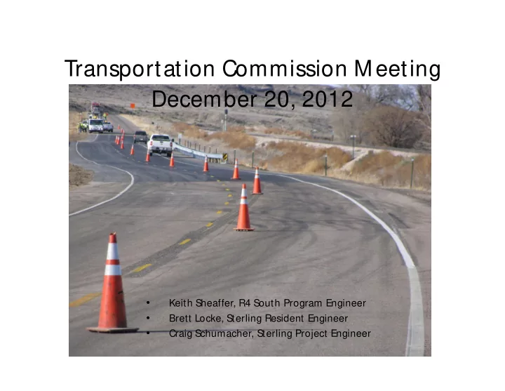
Transportation Commission Meeting December 20, 2012
- Keith Sheaffer, R4 South Program Engineer
- Brett Locke, Sterling Resident Engineer
- Craig Schumacher, Sterling Project Engineer