1
Tight Rectilinear Hulls of Simple Polygons Annika Bonerath, - - PowerPoint PPT Presentation
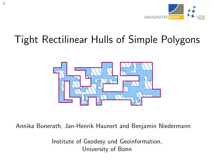
1 Tight Rectilinear Hulls of Simple Polygons Annika Bonerath, Jan-Henrik Haunert and Benjamin Niedermann Institute of Geodesy und Geoinformation, University of Bonn 2 - 1 Motivation Main Goal : Simplification of a polygon P with a polygon Q .
2 - 1
Motivation
Main Goal: Simplification of a polygon P with a polygon Q.
Q Q P P
2 - 2
Motivation
Main Goal: Simplification of a polygon P with a polygon Q.
Q Q
Requirements for Q:
- simple
- C-oriented
- contains P
- cannot be shrunk
(formalization follows on the next slides)
P P
2 - 3
Motivation
Main Goal: Simplification of a polygon P with a polygon Q. Requirements for Q:
- simple
- C-oriented
- contains P
- cannot be shrunk
(formalization follows on the next slides)
P P
2 - 4
Motivation
Main Goal: Simplification of a polygon P with a polygon Q.
Q Q
Requirements for Q:
- simple
- C-oriented
- contains P
- cannot be shrunk
(formalization follows on the next slides) Optimization Goal: few bends, small area, short length
P P
2 - 5
Motivation
Main Goal: Simplification of a polygon P with a polygon Q.
Q Q
Application:
- schematization of plane graph drawings
- travel-time maps that visualize reachable
parts in a road network
- schematic representation of point sets,
instead of using bounding boxes as usually done in data management systems
3
This Paper
Restriction to rectilinear simple input and output polygons.
4 - 1
Formalization of Tight Hulls
Definition: The polygon Q′ is a linear distortion of Q if each edge of Q′ can be scaled and translated such that the polygon Q results.
Q Q′
4 - 2
Formalization of Tight Hulls
Definition: The polygon Q′ is a linear distortion of Q if each edge of Q′ can be scaled and translated such that the polygon Q results.
Q Q′
4 - 3
Formalization of Tight Hulls
Definition: The polygon Q′ is a linear distortion of Q if each edge of Q′ can be scaled and translated such that the polygon Q results.
Q′ = Q
4 - 4
Formalization of Tight Hulls
Definition: A simple polygon Q is a tight hull of another polygon P if Q contains P and there is no linear distortion of Q that lies in Q and contains P.
Q = P P P Q = bounding box of P P
What is a good tight hull?
Q
4 - 5
Formalization of Tight Hulls
Definition: The tight hull Q of P is α-optimal if Q minimizes cost(Q) = α1 · length(Q) + α2 · area(Q) + α3 · bends(Q)
- ver all tight hulls Q′.
P Q P P Q Q
length(Q) bends(Q) area(Q)
5 - 1
Structural Properties
P
Lemma 1: Every vertex of Q on P is a vertex of the maximally subdivided P. Idea of Proof:
e1 e2 w Q v e1 e2 e3 Q v
but then Q is not tight (scale e1 and e3) v is not a vertex of P v is a vertex of P
P P Q
5 - 2
Structural Properties
P
Lemma 1: Every vertex of Q on P is a vertex of the maximally subdivided P. ⇒ use vertices of P for the computation of Q
Q
5 - 3
Structural Properties
Definition: The polyline B is a bridge if,
- it consists of one or two incident line segments forming an “L”
- it starts and ends at vertices of P.
Definition: The region enclosed by B and the polyline of P connecting the same vertices as B is the bag of B.
B P B bag B bag bag bag P P
5 - 4
Structural Properties
⇒ every tight hull can be represented by a set of bridges Definition: The polyline B is a bridge if,
- it consists of one or two incident line segments forming an “L”
- it starts and ends at vertices of P.
5 - 5
Structural Properties
Lemma 2: The bounding box B of P is a tight hull and any other tight hull of P is contained in B.
P B Q
Idea: carve into the bounding box B to generate any tight hull
6 - 1
Decomposition
input P tight hull Q bounding box B
6 - 2
Decomposition
B1 B2 B3 B4
Decompose B into four independent subinstances defined by bridges B1, B2, B3 and B4.
6 - 3
Decomposition
B1 B2 B3 B4 Q1 Q2 Q4 Q3
Decompose B into four independent subinstances defined by bridges B1, B2, B3 and B4. Idea: Solve instances independently and compose solutions.
7 - 1
Decomposition
a b c d f g h i j k
Q1 B1
Decomposition
e
7 - 2
Decomposition
a b c d f g h i j k
Decomposition tree of B1.
B1 e
7 - 3
Decomposition
k B1 a b c d f g h i j k
Decomposition tree of B1.
e
7 - 4
Decomposition
k B1 a b c d f g h i j k
Decomposition tree of B1.
e
7 - 5
Decomposition
a j b k B1 a b c d f g h i j k
Decomposition tree of B1.
e
7 - 6
Decomposition
a j b k B1 a b c d f g h i j k
Decomposition tree of B1.
e
7 - 7
Decomposition
a c j b k B1 a b c d f g h i j k
Decomposition tree of B1.
e
7 - 8
Decomposition
a c j b f k B1 a b c d f g h i j k
Decomposition tree of B1.
e
7 - 9
Decomposition
a c j b d e f k B1 a b c d e f g h i j k
Decomposition tree of B1.
7 - 10
Decomposition
a c j b d e f i k B1 a b c d f g h i j k
Decomposition tree of B1.
e
7 - 11
Decomposition
a c j b d e f g h i k B1 a b c d f g h i j k
Decomposition tree of B1.
e
8 - 1
Decomposition Rules
C1
Decomposition of a bridge B into
- one to three connected bridges C1, C2, and C3,
- each C1, C2, and C3 lies in the bag of B
- the polyline defined by C1, C2, and C3 connects the start and
endpoint of B
- C1, C2, and C3 may not cross each other pairwise
B B B C1 C2 C3 C1 C2
8 - 2
Decomposition Rules
Note: rules guarantee that Q is not self-intersecting
9
Computation
Lemma: For each tight hull there exists a decomposition tree. Observation: Each decomposition of a bridge can be described by two additional points ⇒ all possible decompositions can be enumerated in polynomial time. Use dynamic programming approach to build a decomposition tree of an α-optimal tight hull in O(n4) time.
10
Non-Rectilinear Input Polygon
P P Problem: vertices of Q are not necessarily vertices of the maximally subdivided P Simple Approximative Approach: sample regularly distibuted vertices on the edges of P
11
Conclusion and Outlook
Conclusion:
- non-self intersecting α-optimal tight rectilinear hull in O(n4) time and
O(n2) space Future Work:
- C-oriented tight hulls
- optimal solutions for arbitrary (simple) input polygons
P Q P Q
12