theodolite
play

Theodolite Its essential components are: - a telescope which can - PDF document

COMPONENTS OF A THEODOLITE INTRODUCTION The theodolite is used to measure horizontal and vertical angles. The accuracy with which these angles can be measured ranges from 5mins to 0,1 secs . It is a very important instrument in plane


  1. COMPONENTS OF A THEODOLITE INTRODUCTION • The theodolite is used to measure horizontal and vertical angles. The accuracy with which these angles can be measured ranges from 5mins to 0,1 secs . It is a very important instrument in plane surveying. Theodolite • Its essential components are: - a telescope which can rotate or transit through 360° about a transverse horizontal axis. - The bearings for this horizontal or trunnion axis are mounted in two vertical pillars or standards . The standards are mounted on a horizontal upper plate . - The upper plate rotates through 360° about a vertical or alidade axis, the bearing for the alidade axis is mounted in a lower horizontal plate . - Rotation of the upper plate about the alidade axis is known as 
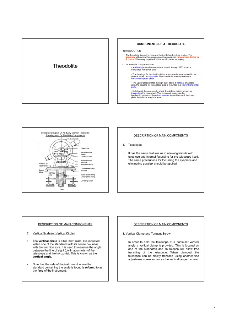
traversing the instrument. The horizontal plates can be levelled by means of three foot screws located beneath the lower plate, in a similar way to a level. Simplified Diagram Of An Early Vernier Theodolite DESCRIPTION OF MAIN COMPONENTS Showing Most Of The Main Components Vertical circle 1. Telescope Telescope • It has the same features as in a level graticule with Vertical circle clamp eyepiece and internal focussing for the telescope itself. Trunnion axis The same precautions for focussing the eyepiece and Vertical circle verniers eliminating parallax should be applied. Altitude bubble Clip screws Plate bubbles Upper plate clamp Lower plate clamp Levelling screw DESCRIPTION OF MAIN COMPONENTS DESCRIPTION OF MAIN COMPONENTS 2. Vertical Scale (or Vertical Circle) 3. Vertical Clamp and Tangent Screw • The vertical circle is a full 360° scale. It is mounted • In order to hold the telescope at a particular vertical within one of the standards with its centre co-linear angle a vertical clamp is provided. This is located on with the trunnion axis. It is used to measure the angle one of the standards and its release will allow free between the line of sight (collimation axis) of the transiting of the telescope. When clamped, the telescope and the horizontal. This is known as the telescope can be slowly transited using another fine vertical angle. adjustment screw known as the vertical tangent screw . • Note that the side of the instrument where the standard containing the scale is found is referred to as the face of the instrument. 1

  2. DESCRIPTION OF MAIN COMPONENTS DESCRIPTION OF MAIN COMPONENTS 4. Upper Plate 5. The Lower Plate • The upper plate is the base on which the standards • The lower plate is the base of the whole instrument. It and vertical circle are placed. Rotation or transiting of houses the foot screws and the bearing for the vertical the upper plate about a vertical (alidade) axis will also axis. It is rigidly attached to the tripod mounting cause the entire standards/telescope assembly to assembly and does not move. rotate in an identical manner. For the instrument to be in correct adjustment it is therefore necessary that the upper plate must be perpendicular to the alidade axis and parallel to the trunnion axis. Also, before the instrument is used, the upper plate must be "levelled". This is achieved by adjustment of three foot screws and observing a precise tube bubble. This bubble is known as the plate bubble and is placed on the upper plate. DESCRIPTION OF MAIN COMPONENTS DESCRIPTION OF MAIN COMPONENTS 6. Horizontal Scale (or Horizontal Circle) 7. The Upper Horizontal Clamp and Tangent Screw. • The horizontal circle is a full 3600 scale. It is often placed between the upper and lower plates with its • The upper horizontal clamp is provided to clamp the centre co-linear with the vertical axis. It is capable of upper plate to the horizontal circle. Once the clamp is full independent rotation about the trunnion axis so that released the instrument is free to traverse through any particular direction may be arbitrarily set to read 360° around the horizontal circle. When clamped, the zero. instrument can be gradually transited around the circle by use of the upper horizontal tangent screw. It is the upper clamp and tangent screw which are used during • It is used to define the horizontal direction in which the a sequence or "round" of horizontal angle telescope is sighted. Therefore a horizontal angle measurements. measurement requires two horizontal scale readings taken by observing two different targets. • The difference between these readings will be the horizontal angle subtended by the two targets at the theodolite station. DESCRIPTION OF MAIN COMPONENTS DESCRIPTION OF MAIN COMPONENTS 8. The Lower Horizontal Clamp and Tangent Screw. 9. Circle Reading and Optical Micrometer • The lower horizontal clamp is provided to clamp the • Modern instruments usually have one eyepiece for horizontal circle to the lower plate. Once the clamp is reading both circles. It is usually located on one of the released the circle is free to rotate about the vertical standards. The vertical and horizontal circles require axis. When clamped, the horizontal circle can be illumination in order to read them. This is usually gradually rotated using the lower-horizontal tangent provided by small circular mirrors which can be angled screw. The lower clamp and tangent screw must only and rotated to reflect maximum light onto the circles. be used at the start of a sequence or "round" of horizontal angle measurements to set the first reading to zero (if so desired). 2

  3. DESCRIPTION OF MAIN COMPONENTS DESCRIPTION OF MAIN COMPONENTS 10. Optical Plumb Comments • Unlike optical levels, theodolites must be set up over 1. Horizontal Clamps and Tangent Screws. fixed control stations, often defined by wooden pegs and nails. Positioning of the instrument must be • Great care must be taken not to confuse the upper and achieved to nail head accuracy. Modern instruments lower horizontal clamps and tangent screws. With the have an optical plumb to achieve this. It consists of an upper clamp released, the instrument rotates around eyepiece set in the lower plate. The line of sight the horizontal circle. With the lower released, the through the eyepiece, which is reflected vertically instrument and circle rotate around the lower plate. downwards beneath the instrument by means of a prism, is precisely in line with the vertical axis. DESCRIPTION OF MAIN COMPONENTS DESCRIPTION OF MAIN COMPONENTS Comments Comments 1. Horizontal Clamps and Tangent Screws. 2. Instrument Station. • Great care must be taken not to confuse the upper and • Since the function of the instrument is to measure lower horizontal clamps and tangent screws. With the vertical and horizontal angles subtended at the upper clamp released, the instrument rotates around instrument, the position of the instrument is important the horizontal circle. With the lower released, the (unlike the position of a level). Theodolites are instrument and circle rotate around the lower plate. therefore set up over control stations which are permanent locations. The art of setting up a theodolite over a station <to nail head accuracy) and getting it • The upper tangent screw moves the instrument level is best demonstrated rather than described. relative to the circle, the lower tangent screw moves the instrument and circle relative to the lower plate. Tangent screws only work when the clamps are tightened, they have limited travel and must not be forced. DESCRIPTION OF MAIN COMPONENTS DESCRIPTION OF MAIN COMPONENTS Comments Comments • When one considers additional features such as illuminating 3. Familiarisation mirrors, eyepiece focussing, a precise plate bubble (possibly a vertical circle precise bubble), an approximate circular bubble), optical plumb and foot screws, one realises that a theodolite is a • On a modern theodolite there should be the following complicated and very expenslve i ns t rument. controls (silver knobs): • Telescope focussing • So regarding the practical side: • Vertical clamp Make sure you understand the function of every control. • Vertical tangent screw Different types of instrument will have different features. • Vertical circle fine adjustment screw (if not an automatic indexing instrument) • Treat the instrument with great care. Never force screws. Never • Microptic adjustment force the instrument into its box. Always thoroughly dry the • Upper horizontal clamp instrument with tissues if it gets wet. Never replace a wet • Lower horizontal clamp (note that on some instruments instrument in its box. Report any accidents or faults. the two horizontal clamps are combined into one). • h) Upper Horizontal tangent screw • i) Lower horizontal tangent screw. 3

Download Presentation
Download Policy: The content available on the website is offered to you 'AS IS' for your personal information and use only. It cannot be commercialized, licensed, or distributed on other websites without prior consent from the author. To download a presentation, simply click this link. If you encounter any difficulties during the download process, it's possible that the publisher has removed the file from their server.

Recommend


More recommend