The Royal Mail Ship Titanic: Did a Metallurgical Failure Cause a - - PDF document

the royal mail ship titanic
SMART_READER_LITE
LIVE PREVIEW

The Royal Mail Ship Titanic: Did a Metallurgical Failure Cause a - - PDF document

Archaeotechnology Feature The Royal Mail Ship Titanic: Did a Metallurgical Failure Cause a Night to Remember? Katherine Felkins, H.P. Leighly, Jr., and A. Jankovic The Titanic . (Photo courtesy of the Titanic Historical Society.) A n o e d


slide-1
SLIDE 1

JOM • January 1998 12

Over the last 30 years, there has been a discernible increase in the number of scholars who have focused their research on early industrial organizations, a field of study that has come to be known as Archaeotechnology. Archaeologists have conducted fieldwork geared to the study of ancient technologies in a cultural context and have drawn on the laboratory analyses developed by materials scientists as one portion of their interpretive program. Papers for this bimonthly department are solicited and reviewed by Robert

  • M. Ehrenreich of the National Materials Advisory Board of the National Research Council.

T h e b

  • w
  • f

t h e s h i p a s i t a p p e a r e d d u r i n g a 1 9 8 6 e x p e d i t i

  • n

. ( P h

  • t
  • c
  • u

r

  • t

e s y

  • f

W

  • d

s H

  • l

e O c e a n

  • g

r a p h i c I n s t i t u t i

  • n

. ) A n

  • t

h e r v i e w

  • f

t h e Titanic d u r i n g a 1 9 8 6 e x p e d i t i

  • n

. ( P h

  • t
  • c
  • u

r t e s y

  • f

W

  • d

s H

  • l

e O c e a n

  • g

r a p h i c I n s t i

  • t

u t i

  • n

. )

The Royal Mail Ship Titanic:

Did a Metallurgical Failure Cause a Night to Remember?

Katherine Felkins, H.P. Leighly, Jr., and A. Jankovic

The Titanic. (Photo courtesy of the Titanic Historical Society.) The ship during a 1986 expedition. (Photo courtesy

  • f Woods Hole Oceanographic Institution.)

Editor’s Note: A hypertext-enhanced version of this article can be found on the TMS web site at http:// www.tms.org/pubs/journals/JOM/9801/Felkins- 9801.html.

INTRODUCTION In the early part of this century, the

  • nly means of transportation for trav-

elers and mail between Europe and North America was by passenger

  • steamship. By 1907, the Cunard

Steamship Company introduced the largest and fastest steamers in the North Atlantic service: the Lusitania and the Mauritania. Each had a gross tonnage of 31,000 tons and a maxi- mum speed of 26 knots. In that year, Lord William James Pirrie, managing director and controlling chair of the Irish shipbuilding company Harland

A metallurgical analysis of steel taken from the hull of the Titanic’s wreckage reveals that it had a high ductile- brittle transition temperature, making it unsuitable for service at low temperatures; at the time of the collision, the temperature of the sea water was –2°C. The analysis also shows, however, that the steel used was probably the best plain carbon ship plate available at the time of the ship’s construction.

and Wolff, met with J. Bruce Ismay, managing director of the Oceanic Steam Navigation Company, better known as the White Star Line (a name taken from its pennant). During this meeting, plans were made to con- struct three enormous new White Star liners to compete with the Lusitania and Mauritania on the North Atlantic by establishing a three-ship weekly steamship service for passen- gers and mail between Southampton, England, and New York City. This decision required the construction of a trio of luxurious steamships. The first two built were the RMS Olympic and the RMS Titanic; a third ship, the RMS Britannic, was built later (the fate of the sister ships is described in

Feature Archaeotechnology

slide-2
SLIDE 2

1998 January • JOM 13 THE LIVES OF THE SISTER SHIPS

The RMS Olympic made more than 500 round trips between Southampton and New York before it was retired in 1935 and was finally broken up in 1937. In 1919, it became the first large ship to be converted from coal to oil. On May 15, 1934, as the Olympic approached New York, it struck the Nantucket light ship during a heavy fog, cutting it in half. Of the crew, four were drowned, three were fatally injured, and three were rescued.1 The third ship of the series, the Britannic, had a short

  • life. While it was being constructed, the Titanic was
  • sunk. Immediately, the design was changed to provide

a double hull and the bulkheads were extended to the upper deck. Before the Britannic was completed, World War I broke out, and the vessel was converted into a hospital ship. On November 21, 1916, it was proceeding north through the Aegean Sea east of Greece when it struck a mine. Because the weather had been warm, many of the portholes had been opened, hence rapid flooding of the ship occurred. The ship sank in 50 minutes with a small loss of life; one of the loaded life boats was drawn into a rotating propeller.

Figure 1. The Titanic under construction at the Harland and Wolff shipyard in Ireland. (Photo courtesy of the Titanic Historical Society.)

the sidebar). The Titanic be- gan its maiden voyage to New York just before noon on April 10, 1912, from Sou- thampton, Eng-

  • land. Two days

later at 11:40 P.M., Greenland time, it struck an ice- berg that was three to six times larger than its

  • wn mass, dam-

aging the hull so that the six for- ward compart- ments were rup-

  • tured. The flood-

ing of these com- partments was sufficient to cause the ship to sink within two hours and 40 minutes, with a loss of more than 1,500 lives. The scope of the tragedy, coupled with a detailed histori- cal record, have fueled endless fascina- tion with the ship and debate over the reasons as to why it did in fact sink. A frequently cited culprit is the quality of the steel used in the ship’s construction. A metallurgical analysis of hull steel recovered from the ship’s wreckage pro- vides a clearer view of the issue. THE CONSTRUCTION The three White Star Line steamships were 269.1 meters long, 28.2 meters maxi- mum wide, and 18 meters tall from the water line to the boat deck (or 53 meters from the keel to the top of the funnels), with a gross weight of 46,000 tons. Be- cause of the size of these ships, much of the Harland and Wolff shipyard in Belfast, Ireland, had to be rebuilt before construction could begin; two larger ways were built in the space originally

  • ccupied by three smaller ways. A new

gantry system with a larger load-carry- ing capacity was designed and installed to facilitate the construction of the larger

  • ships. The Titanic under construction at

the shipyard is shown in Figure 1. The ships were designed to provide accommodations superior to the Cunard ships, but with-

  • ut greater speed.

The first on- board swimming pools were in- stalled as was a gymnasium that included an elec- tric horse and an electric camel, a squash court, a number of row- ing machines, and stationary bicycles, all supervised by a staff of professional

  • instructors. The public rooms for the

first-class passengers were large and el- egantly furnished with wood paneling, stained-glass windows, comfortable lounge furniture, and expensive carpets. The decor of the first class cabins, in addition to being luxurious, differed in style from cabin to cabin. As an extra feature on the Titanic, the Café Parisienne

  • ffered superb cuisine.

The designed speed for these ships was 21–22 knots, in contrast to the faster Cunard ships. To achieve this speed, each ship had three propellers; each out- board propeller was driven by a sepa- rate four-cylinder, triple expansion, re- ciprocating steam engine.2 The center propeller was driven by a low-pressure steam turbine using the exhaust steam from the two reciprocating engines. The power plant was rated at 51,000 I.H.P. To provide the necessary steam for the power plant, 29 boilers were available, fired by 159 furnaces. In addition to pro- pelling the ship, steam was used to gen- erate electricity for various purposes, distill fresh water, refrigerate the perish- able food, cook, and heat the living space. Coal was burned as fuel at a rate of 650 tons per day when the ship was underway. Stokers moved the coal from the bunkers into the furnaces by hand. The bunkers held enough coal for a ten-day voyage. The remodeled shipyard at Har- land and Wolff was large enough for the construc- tion of two large ships simulta-

  • neously. The keel
  • f the Olympic

was laid Decem- ber 16, 1908, while the Titanic‘s keel followed on March 31, 1909. The Olympic was launched on Oc- tober 20, 1910, and the Titanic on May 31, 1911. In the early 20th century, ships were constructed using wrought- iron rivets to attach steel plates to each

  • ther or to a steel frame. The frame itself

was held together by similar rivets. Holes were punched at appropriate sites in the steel-frame members and plates for the insertion of the rivets. Each rivet was heated well into the austenite tempera- ture region, inserted in the mated holes

  • f the respective plates or frame mem-

bers, and hydraulically squeezed to fill the holes and form a head. Three million rivets were used in the construction of the ship. The construction of the Titanic was delayed due to an accident involving the

  • Olympic. During its fifth voyage,3 the

Olympic collided with the British cruiser, HMS Hawke, damaging its hull near the bow on the port (left) side. This occurred in the Solent off Southampton on Sep- tember 20, 1911. The Olympic was forced to return to Belfast for repairs. To accom- plish the repairs in record time and to return the ship to service promptly, workmen were diverted from the Titanic to repair the Olympic. On April 2, 1912, the Titanic left Belfast for Southampton and its sea trials in the Irish Sea. After two days at sea, the Ti- tanic, with its crew and officers, arrived at Sout- hampton and tied up to Ocean Dock

  • n April 4. Dur-

ing the next sev- eral days, the ship was provisioned and prepared for its maiden voy- age.

slide-3
SLIDE 3

JOM • January 1998 14

Figure 2. An optical micrograph of steel for the hull of the Titanic in (a) longitudinal and (b) transverse directions, showing banding that resulted in elongated pearlite colonies and MnS particles. Etchant is 2% Nital. b 100 µm a 100 µm Table I. A Summary of Damaged Areas in the Hull by Compartment*6 Computer Compartment Calculations (m2) Fore Peak 0.056 Cargo Hold 1 0.139 Cargo Hold 2 0.288 Cargo Hold 3 0.307 Boiler Room 6 0.260 Boiler Room 5 0.121 Total Area 1.171

* The compartments are listed in order from the bow to- ward the stern.

Figure 3. The microstructure of ASTM A36 steel showing ferrite and pearlite. The mean grain diameter is 26.173 µm. Etchant is 2% Nital. 20 µm Table II. The Composition of Steels from the Titanic, a Lock Gate, and ASTM A36 Steel C Mn P S Si Cu O N Mn:S Ratio Titanic Hull Plate 0.21 0.47 0.045 0.069 0.017 0.024 0.013 0.0035 6.8:1 Lock Gate* 0.25 0.52 0.01 0.03 0.02 — 0.018 0.0035 17.3:1 ASTM A36 0.20 0.55 0.012 0.037 0.007 0.01 0.079 0.0032 14.9:1

* Steel from a lock gate at the Chittenden ship lock between Lake Washington and Puget Sound, Seattle, Washington.

THE VOYAGE On the morning of April 10, 1912, the passengers and remaining crew mem- bers came to Ocean Dock to board the ship for its maiden voyage. Shortly be- fore noon, the Titanic cast off and nar- rowly avoided colliding with a docked passenger ship, the New York (which broke its mooring cables due to the surge

  • f water as the huge ship passed), before

proceeding down Southampton Water into the Solent and then into the English

  • Channel. After a stop at Cherbourg,

France, on the evening of April 10th and a second stop at Queenstown (now Cobh), Ireland, the next morning to take

  • n more passengers and mail, the Titanic

headed west on the Great Circle Route toward the Nantucket light ship 68 kilo- meters south of Nantucket Island off the southeast coast of Massachusetts. The Irish coast was left behind about dusk

  • n April 11.

During the early afternoon of April 12, the French liner, La Touraine, sent advice by radio of ice in the steamship lanes, but this was not uncommon during an April

  • crossing. This advice was sent nearly 60

hours before the fatal collision. As the voyage continued, the warnings of ice received by radio from other ships be- came more frequent. With time, these warnings gave more accurate informa- tion on the location of the icefields and it became apparent that a very large icefield lay in the ship’s course. On the basis of several reports after the accident, it was estimated that the icefield was 120 km long on a northeast-southwest axis and 20 km wide;4 there is evidence that the Titanic was twice diverted to the south in a vain effort to avoid the fields. The ship continued at a speed of about 21.5 knots. On the moonless night of April 14, the

  • cean was very calm and still. At 11:40

P.M., Greenland time, the lookouts in the

crow’s nest sighted an iceberg immedi- ately ahead of the ship; the bridge was

  • alerted. The duty officer ordered the ship

hard to port and the engines reversed. In about 40 seconds, as the Titanic was be- ginning to respond to the change in course, it collided with an iceberg esti- mated to have a gross weight of 150,000– 300,000 tons. The iceberg struck the Ti- tanic near the bow on the starboard (right) side about 4 m above the keel. During the next 10 seconds, the iceberg raked the starboard side of the ship’s hull for about 100 m, damaging the hull plates and popping rivets, thus opening the first six of the 16 watertight compart- ments formed by the transverse bulk-

  • heads. Inspection shortly after the colli-

sion by captain Edward Smith and Tho- mas Andrews, a managing director and chief designer for Harland and Wolff and chief designer of the Titanic, revealed that the ship had been fatally damaged and could not survive long. At 2:20 A.M., April 15, 1912, the Titanic sank with the loss of more than 1,500 lives. THE SINKING Initial studies of the sinking proposed that a continuous gash in the hull 100 m in length was created by the impact with the iceberg. More recent studies indicate that discontinuous damage occurred along the 100 m length of the hull. After the sinking, Edward Wilding, design engineer for Harland and Wolff, esti- mated that the collision had created open- ings in the hull totaling 1.115 m2, based

  • n the reports of the rate of flooding

given by the survivors.5 This damage to the hull was sufficient to cause the ship to sink. Recent computer calculations by Hackett and Bedford6 using the same survivors’ information, but allocating the damage individually to the first six com- partments that were breached is given in Table I. This shows a total damage area

  • f 1.171 m2, which is a slightly larger area

than the estimate by Wilding. At the time of the accident, there was disagreement among the survivors as to whether the Titanic broke into two parts as it sank or whether it sank intact. On September 1, 1985, Robert Ballard5 found the Titanic in 3,700 m of water on the

  • cean floor. The ship had broken into

two major sections, which are about 600 m apart. Between these two sections is a debris field containing broken pieces

  • f steel hull and bulkhead plates, rivets

that had been pulled out, dining-room cutlery and chinaware, cabin and deck furniture, and other debris. The only items to survive at the site are those made of metals or ceramics. All items made from organic materials have long since been consumed by scaven- gers, except for items made from leather such as shoes, suitcases, and mail sacks; tanning made leather unpalatable for the scavengers. The contents of the leather suitcases and mail sacks, having been protected, have been retrieved and

  • restored. Ethical and legal issues associ-

ated with the recovery of such items are described in the sidebar authored by C.R. McGill. THE STEEL Composition During an expedition to the wreckage in the North Atlantic on August 15, 1996, researchers brought back steel from the hull of the ship for metallurgical analy-

  • sis. After the steel was received at the

University of Missouri–Rolla, the first step was to determine its composition. The chemical analysis of the steel from

slide-4
SLIDE 4

1998 January • JOM 15

F i g u r e B . L e

  • n

a r d

  • D

e C a p r i

  • a

n d K a t e W i n s l e t w a d e t h r

  • u

g h t h e f i r s t c l a s s d i n i n g s a l

  • n

i n a s c e n e f r

  • m

Titanic. ( P h

  • t
  • b

y M e r i e W . W a l l a c e a n d c

  • u

r t e s y

  • f

P a r a m

  • u

n t P i c t u r e s a n d T w e n t i e t h C e n t u r y F

  • x

. )

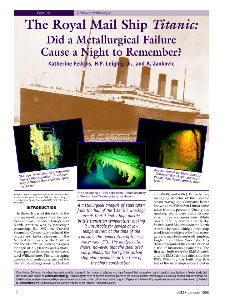
THE TITANIC IN THE ARTS

Since its tragic voyage in 1912, the RMS Titanic has captured the attention and the imagination of the world. The shocking, untimely death of more than 1,500 people, the irony of the “unsinkable” ship doing the unthinkable

  • n its maiden voyage, and the first-hand accounts of the

approximately 700 survivors have spurred countless debates and discussions on the reasons for the ship’s

  • demise. As the debate continues in scientific, historical,

and even legal circles, the ship, her crew, and passen- gers have been memorialized time and again through the arts. Numerous accounts of the ship and her sisters, the Olympic and Britannic, have been published during the past 80 years; some have been fac- tual, others fictionalized adaptations. One of the first non-newspaper accounts, and one of the most popular, is the book A Night to Remember, written by Walter Lord in 1955. According to Lord, in the four decades follow- ing the sinking there was no worldwide general interest in the ship and no historical accounts of the voyage. Based on historical materials and first-hand accounts of survivors and witnesses, A Night to Remember is reportedly the first book to give a factual account of the night the ship sank. A nearly countless number of books have followed. On film, the Titanic has been the subject for a number

  • f docudramas and early disaster films. One of the first

was Titanic, done in 1926. About 16 years later, Herbert Selpin directed a German film on the subject. Arguably the most well-known film on the Titanic is the same- titled film directed by Jean Negulesco in 1953. A fiction- alized account of one family on the Titanic, the film won two Academy Awards that year for Best Art Direction and Best Original Screenplay. The movie, starring Barbara Stanwyck and Clifton Webb, set the standard for early disaster films in the United States. On the other side of the Atlantic, English filmmakers adapted Lord’s A Night to Remember into a film of the same name in

  • 1958. Unlike the romanticized U.S. version, producer

William MacQuitty and director Eric Ambler created a gritty, realistic docudrama using state-of-the-art special

  • effects. For one of the first times in filmmaking, the

actors worked on sets that were tilted by hydraulic jacks, creating loud, grinding noises that imitated the sounds the ship would have made in sinking. When Robert Ballard and an American-French search team discovered the site of the Titanic in 1985, interest in the ship and her history resurged. Images of the ship

  • n the sea floor taken by underwater robots more than

70 years after the disaster brought the Titanic and its saga back into international pop culture. Today, there are videos, CD-ROMs, and even computer games available that allow users to become a passenger on the

  • ship. The emergence of the Internet has enabled people

from around the world to access a wealth of photo- graphs, animated film clips, sound clips, and historical information on the subject or join groups composed of other Titanic enthusiasts. Plays on the Titanic appear ev- erywhere from dinner theaters through-

  • ut the United States to the Great White

Way—Broadway. In 1997, the Broad- way musical Titanic won a Tony Award for the Best Musical, released a top- selling cast album, and, on the aver- age, surpassed ticket sales for any show on Broadway. The most recent addition to the collection is Titanic, a 1997 film by Twentieth Century Fox and Para- mount Pictures that focuses on the love story of two young passen-

  • gers. Released on December 19,

the film reportedly became the most expensive film ever made ($200 million according to some reports) in its attempt to be as historically accurate as possible. To assist the production crew, a group of historians and experts

  • n the Titanic were brought aboard as consultants,

including Don Lynch, the historian for the Titanic Histori- cal Society, and Ken Marschall, noted artist of the ship. Shipbuilders Harland and Wolff provided copies of the

  • riginal blueprints of the Titantic and Thomas Andrews’
  • wn notebook on the ship’s design features to the

production crew. In addition, the manufacturer of the

  • riginal carpeting, which is still in business, had the
  • riginal patterns on file and reproduced

the dyes. To make the ship as authentic as possible, director James Cameron char- tered a Russian scientific vessel and made 12 dives to the actual wreck site to film the interior of the ship. Using an

  • ff-the-shelf 35 mm camera modified

to fit in custom-made titanium hous- ings, the camera brought back reels of film showing the ship’s interior—ev- erything from window frames, light fixtures, a brass door plate, and even a bronze fireplace box. “We were able to come back with this rich harvest of film and video images,” Cameron said. ‘We sent our re- mote vehicle inside and explored the interiors. We literally saw things that no one has seen since 1912, since the ship went down. We’ve integrated these images into the fabric of the film and that reality has a profound impact on the emotional power of the film.” The complete set was built at Fox Baja Studios in Mexico beginning on May 30, 1996; it was completed 100 days later. The set featured a 64.2 million liter exterior seawater tank (the largest shooting tank in the world). Whereas the 1953 movie used a 8.5 m model of the ship, the 1997 movie recreated a nearly full size, 236 m long exterior set of the Titanic standing nearly 14 m tall from the water line to the boat deck floor, with its four funnels towering another 16 m. To recreate the sinking of the ship, several exterior and interior shooting tanks were used. (A still from the movie appears on the cover of this issue.) The first-class dining saloon and three-story grand staircase were constructed on a hydraulic platform at the bottom of the 9 m interior tank designed to be angled and flooded with 19 million liters of filtered seawater drawn from the

  • cean. Camera cranes and jacks were placed above

the ship for the final filming stages, when the ship was separated into two pieces. The front half was sunk in 12 m of water using hydraulics. Preliminary reviews of the movie at the time this issue goes to press in early December (prior to the movie’s release) have been very good, and the movie has already made several top ten lists for 1997, including

  • ne by Rolling Stone magazine. The Hollywood Re-

porter says, “Titanic’s visual and special effects tran- scend state-of-the-art workmanship . . . Pencil [Gloria] Stuart in for a likely best supporting actress nomination this winter. Also on the Oscar front, clear the deck for multiple technical nominations. . . . The iron monster is a heart stopper.” It is doubtful that the Titanic will be the last film made about this ill-fated ship. Through the years, the saga of the Titanic has taken on a life of its own. As songs, poems, historical accounts, and novels continue to be created, the story has merged into modern urban folklore. “The tragedy of the Titanic has assumed an almost mythic quality in our collective imagination,” Cameron

  • said. “Titanic is not just a cautionary tale—a myth, a

parable, a metaphor for the ills of mankind. It is also a story of faith, courage, sacrifice, and above all else, love.” Tammy M. Beazley JOM

F i g u r e A . T h e R M S T i t a n i c l e a v e s p

  • r

t i n t h e 1 9 9 7 m

  • v

i e T i t a n i c . ( P h

  • t
  • b

y M e r i e W . W a l l a c e a n d c

  • u

r t e s y

  • f

P a r a m

  • u

n t P i c t u r e s a n d T w e n t i e t h C e n t u r y F

  • x

. )

the hull is given in Table II. The first item noted is the very low nitrogen content. This indicates that the steel was not made by the Bessemer process; such steel would have a high nitrogen content that would have made it very brittle, particu- larly at low temperatures. In the early 20th century, the only other method for making structural steel was the open- hearth process. The fairly high oxygen and low silicon content means that the steel has only been partially deoxidized, yielding a semikilled steel. The phos- phorus content is slightly higher than normal, while the sulfur content is quite high, accompanied by a low manganese

  • content. This yielded a Mn:S ratio of

6.8:1—a very low ratio by modern stan-

  • dards. The presence of relatively high

amounts of phosphorous, oxygen, and sulfur has a tendency to embrittle the steel at low temperatures. Davies7 has shown that at the time the Titanic was constructed about two-thirds

  • f the open-hearth steel produced in the

United Kingdom was done in furnaces having acid linings. There is a high prob-

slide-5
SLIDE 5

JOM • January 1998 16 THE ETHICAL AND LEGAL ISSUES IN SALVAGING THE TITANIC

Author’s Note: The author thanks Michael McCaughan of the Ulster Folk and Transport Museum, Northern Ireland, for his assistance in the prepa- ration of this sidebar.

The Titanic has engaged the attention of a rapt world audience for almost a century now. As the most famous and historic of all shipwrecks, it is enshrouded in a cloak

  • f mystery and controversy; the traumatic effect that the

loss of the ship had on the public at the time of the disaster has not abated, making the Titanic seem al- most eternal. Numerous plans to salvage the ship and its cargo were developed over the 73 years that the Titanic lay undiscovered 4 km below the ocean surface. It was not until 1985 that salvage became feasible, when Robert Ballard of the Oceanographic Institute in Woods Hole, Massachusetts, discovered the ship’s exact location as part of a joint American-French research team. Serious issues were immediately raised over the controversial question of salvage rights, the main issue being that the wreck lay in international waters; there is no legal protection in international waters for wrecks of historical or archaeological significance. In such cases, wrecks are subject to salvage law, which stipulates that the first salvor on the site has exclusive rights to the site. Thus, other salvors are prevented from accessing the site as long as expeditions are being planned and conducted to recover artifacts from the wreck. Robert Ballard could not legally claim salvage rights to the wreck, since he discovered it while working on a government research project. The French Oceanogra- phy Institute, which was the French component of the joint American-French research team and had received little acknowledgement for its contribution in the discov- ery of the wreck, had no such constraints, however. It was soon involved in the formation of the commercial salvage company that was to become RMS Titanic, Inc. More than 1,500 people—rich and poor, represent- ing more than 20 countries—perished in the disaster. The ship had broken into two separate parts, with the stern section lying about 804.5 m beyond the bow

  • portion. A huge field of debris covers the ocean floor

between the two pieces. RMS Titanic, Inc., stated early

  • n that they only intended to record the site; recover,

conserve, preserve, and tour just those artifacts recov- ered from the debris field; and keep the collection together rather than sell it to individual buyers around the world. The culmination of the project would be a Titanic Memorial Museum in which all of the artifacts recovered would be kept. (It should be noted, however, that RMS Titanic, Inc., has recently made available for sale to the general public authenticated coal from the sea bed.) Reaction was strong and immediate. Individuals and

  • rganizations from around the world vehemently op-

posed the idea of salvage work being done on the Titanic, claiming that the wreck was a grave site and should be left undisturbed as a memorial to those who

  • died. Such organizations as the Titanic Historical Soci-

ety (the largest and most senior of the Titanic enthusiast bodies) of the United States and the Ulster Titanic Society of Northern Ireland (where the ship was built) set themselves against the salvage operation. Robert Ballard, who strongly believes in the sanctity of the site, worked to get a U.S. federal law passed making it illegal to buy or sell artifacts from the site in the United States. Other individuals and institutions allied themselves with the salvage, provided that it was done well and in good taste. They were concerned that artifacts would be sold and dispersed if a company other than RMS Titanic, Inc., were the salvors dealing with the wreck; unscrupulous salvors interested only in pure commer- cial profit would not employ the same sort of painstaking recording, recovery, and conservation methods that RMS Titanic, Inc., used to retrieve materials recovered during the four research and discovery expeditions conducted between 1987 and 1996. Interestingly, al- though the Ulster Titanic Society opposes the salvage

  • f the wreck, the society believes that as long as salvage

work continues, RMS Titanic, Inc., is the best salvor to do the job. In the face of serious international and, at times, hostile criticism from the public, maritime archaeolo- gists, and museum professionals, the National Maritime Museum of Greenwich joined RMS Titanic, Inc., in a partnership to present the first exhibition of artifacts recovered from the wreck. In 1994–95, 150 of the several thousand artifacts recovered from the debris field were displayed in an exhibition titled “Wreck of the Titanic.” The exhibition was billed as the “largest ever public display of Titanic artifacts” and was a huge success in terms of audience attendance and media

  • coverage. More than 500,000 visitors saw the show.

The exhibit brought the museum into direct conflict with the International Congress of Maritime Museums (ICMM), however, of which it is a member. The museum and ICMM disagreed on the subject of salvors and salvage law. The ICMM was concerned that the exhibi- tion included artifacts recovered from the site since 1990, and “relics raised illegally or in inappropriate circumstances after . . . 1990 . . . are considered out-of- bounds for ICMM-member museums.”1 Richard Ormond of the National Maritime Museum claimed that “the objectives of the exhibition were to demonstrate the technical achievement of finding and exploring the site, to show conservation techniques and the extraordinary survival of objects on the sea bed, and to examine the controversy in detail.”2 The museum stressed that none of the artifacts on display came from the hull of the ship, which was the true grave site of the

  • victims. Michael McCaughan, a Titanic expert from the

Ulster Folk and Transport Museum in Northern Ireland visited the exhibition and felt that the “150 artifacts were displayed sensitively in a variety of contexts . . . Funda- mentally this was not an exhibit about the past, but about the present and its appropriation of the past. The exhibit was not a requiem for the dead, nor did it address the metaphorical meaning of Titanic. Rather, it was an enshrinement of the triumphs of deep-sea exploration and the reviving wonders of conservation laboratories.”3 Despite the controversy and arguments over the salvage work conducted by RMS Titanic, Inc., there is no doubt whatsoever that the company’s work is legal. RMS Titanic, Inc., was granted salvor-in-possession rights to the wreck by a U.S. federal court in 1994. Despite a challenge, these rights were reconfirmed in 1996, giving the company exclusive rights to own arti- facts recovered from the wreck. The 1996 judgment took into consideration the site recordings, artifact con- servation, and commitment of RMS Titanic, Inc., to keep the artifact collection together for public display.

References

  • 1. G. Henderson, “Underwater Archaeology and the Titanic: The ICMM

View,” The IXth International Congress of Maritime Museums: Proceed- ings (U.K.: National Maritime Museum, 1996), pp. 64–68.

  • 2. R. Ormond, “Titanic and Underwater Archaeology: The National Mari-

time Museum View,” The IXth International Congress of Maritime Muse- ums: Proceedings (U.K.: National Maritime Museum, 1996), pp. 59–63.

  • 3. M. McCaughan, “Exhibit Review of the National Maritime Museum,

Reading the Relics: Titanic Culture and the Wreck of the Titanic Exhibit,” Material History Review, 43 (1996), pp. 68–72.

Carmel R. McGill Consultant

Table III. A Comparison of Tensile Testing of Titanic Steel and SAE 1020 Titanic SAE 102011 Yield Strength 193.1 MPa 206.9 MPa Tensile Strength 417.1 MPa 379.2 MPa Elongation 29% 26% Reduction in Area 57.1% 50% 10 µm Figure 4. A scanning electron micrograph of the etched surface of the Titanic hull steel showing pearlite colonies, ferrite grains, an elongated MnS particle, and nonmetallic in-

  • clusions. Etchant is 2% Nital.

20 µm Figure 5. A scanning electron micrograph of a Charpy impact fracture surface newly created at 0°C, showing cleavage planes containing ledges and protruding MnS particles.

ability that the steel used in the Titanic was made in an acid-lined open-hearth furnace, which accounts for the fairly high phosphorus and high sulfur con-

  • tent. The lining of the basic open-hearth

furnace will react with phosphorus and sulfur to help remove these two impuri- ties from the steel. It is likely that all or most of the steel came from Glasgow, Scotland. Included in Table II are the composi- tions of two other steels: steel used to construct lock gates at the Chittenden Ship Lock between Lake Washington and Puget Sound at Seattle, Washing- ton,8 and the composition of a modern steel, ASTM A36. The ship lock was built around 1912, making the steel about the same age as the steel from the Titanic. Metallography Standard metallographic techniques were used to prepare specimens taken from the hull plate of the Titanic for

  • ptical microscopic examination. After

grinding and polishing, etching was done with 2% Nital. Because earlier work by Brigham and Lafrenière9 showed severe banding in a specimen of the steel, speci- mens were cut from the hull plate in both the transverse and longitudinal direc-

  • tions. Figure 2 shows the microstructure
  • f the steel. In both micrographs, it is
slide-6
SLIDE 6

1998 January • JOM 17

5 µm Figure 8. Shear fracture percent from Charpy impact tests versus temperature for longitudi- nal and transverse Titanic specimens and ASTM A36 steel. Figure 6. A scanning electron micrograph showing a fractured MnS particle protruding edge-on from the fracture surface.13 Figure 7. Charpy impact energy versus tem- perature for longitudinal and transverse Ti- tanic specimens and ASTM A36 steel.

apparent that the steel is banded, al- though the banding is more severe in the longitudinal section. In this section, there are large masses of MnS particles elon- gated in the direction of the banding. The average grain diameter is 60.40 µm for the longitudinal microstructure and 41.92 µm for the microstructure in the transverse direction. In neither micro- graph can the pearlite be resolved. For comparison, Figure 3 is a micrograph of ASTM A36 steel, which has a mean grain diameter of 26.173 µm. Figure 4 is a scanning electron micros- copy (SEM) micrograph of the polished and etched surface of steel from the Ti-

  • tanic. The pearlite can be resolved in this
  • micrograph. The dark gray areas are
  • ferrite. The very dark elliptically shaped

structure is a particle of MnS identified by energy-dispersive x-ray analysis (EDAX). It is elongated in the direction

  • f the banding, suggesting that banding

is the result of the hot rolling of the steel. There is some evidence of small nonme- tallic inclusions and some of the ferrite grain boundaries are visible. Tensile Testing The steel plate from the hull of the Titanic was nominally 1.875 cm thick, while the bulkhead plate had a thickness

  • f 1.25 cm. Corrosion in the salt water

had reduced the thickness of the hull plate so that it was not possible to ma- chine standard tensile specimens from

  • it. A smaller tensile specimen with a

reduced section of 0.625 cm diameter and a 2.5 cm gage length was used.10 The tensile-test results are given in Table III. These data are compared with tensile-test data for an SAE 1020 steel, which is similar in composition. The steel from the Titanic has the lower yield strength, probably due to a larger grain

  • size. The elongation increases as well,

again due to a larger grain size. Charpy Impact Tests Charpy impact tests12 were performed

  • ver a range of temperatures from –55°C

to 179°C on three series of standard Charpy specimens: a series of specimens machined with the specimen axis paral- lel to the longitudinal direction in the hull plate from the Titanic, a series ma- chined in the transverse direction, and a series made from modern ASTM A36

  • steel. A Tinius Olsen model 84 universal

impact tester was used to determine the impact energy to fracture for several specimens at the selected test tempera-

  • tures. A chilling bath or a circulating air

laboratory oven was used to prepare the specimens for testing at specific tem-

  • peratures. The specimens were allowed

to soak in the appropriate apparatus for at least 20 minutes at the selected tem-

  • perature. Pairs of specimens were tested

at identical test temperatures. Figure 5 is an SEM micrograph of a freshly fractured surface of a longitudi- nal Charpy specimen tested at 0°C. The cleavage planes, (100) in ferrite, are quite

  • apparent. There are cleavage plane sur-

faces at different levels that are defined by straight lines. These straight lines are steps connecting parallel cleavage planes; the edges are parallel to the [010]

  • direction. The crystallographic surfaces
  • f the risers are the (001) plane. In addi-

tion, there are curved slip lines on the cleavage planes. Particles of MnS identified by EDAX can be observed. Some of the MnS par- ticles exist as protrusions from the sur-

  • face. These protrusions were pulled out
  • f the complimentary fracture surface.

In addition, there are the intrusions re- maining after the MnS particles have been pulled out of this fracture surface. One of the pearlite colonies lying in the fracture surface is oriented so that the ferrite and cementite plates have been

  • resolved. Figure 6 shows a fractured

lenticular MnS particle that protrudes edge-on from the fractured surface.13 There are slip lines radiating away from the MnS particle. Figure 7 is a plot of the impact energy versus temperature for the three series

  • f specimens. At higher temperatures,

the specimens prepared from the hull plate in the longitudinal direction have substantially better impact properties than for the transverse specimens. At low temperatures, the impact energy required to fracture the longitudinal and transverse specimens is essentially the

  • same. The severe banding is certainly

the cause of the differences in the impact energy to cause fracture at elevated tem-

  • peratures. The specimens made from

ASTM A36 steel have the best impact

  • properties. The ductile-brittle transition

temperature determined at an impact energy of 20 joules is –27°C for ASTM A36, 32°C for the longitudinal speci- mens made from the Titanic hull plate, and 56°C for the transverse specimens. It is apparent that the steel used for the hull was not suited for service at low

  • temperatures. The seawater temperature

at the time of the collision was –2°C. Comparing the composition of the Ti- tanic steel and ASTM A36 steel shows that the modern steel has a higher man- ganese content and lower sulfur con- tent, yielding a higher Mn:S ratio that reduced the ductile-brittle transition tem- perature substantially. In addition, ASTM A36 steel has a substantially lower phosphorus content, which will also lower the ductile-brittle transition tem-

  • perature. Jankovic8 found that the duc-

tile-brittle transition temperature for the Chittenden lock gate steel was 33°C. The longitudinal specimens of the Titanic hull steel made in the United Kingdom and those specimens from the Chittenden lock steel made in the United States have nearly the same ductile-brittle transition temperature. Shear Fracture Percent At low temperatures where the im- pact energy required for fracture is less, a faceted surface of cleaved planes of ferrite is observed, indicating brittle frac-

  • ture. At elevated temperatures, where

the energy to cause fracture is greater, a ductile fracture with a shear structure is

  • bserved. Figure 8 is a plot of the shear

fracture percent versus temperature. There is a fairly strong similarity be

slide-7
SLIDE 7
slide-8
SLIDE 8