
SLIDE 1
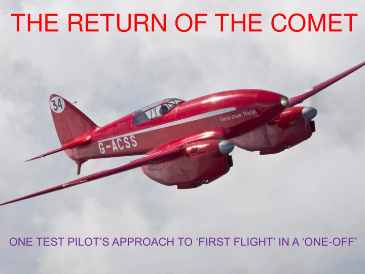
THE RETURN OF THE COMET
ONE TEST PILOT’S APPROACH TO ‘FIRST FLIGHT’ IN A ‘ONE-OFF’
THE RETURN OF THE COMET ONE TEST PILOTS APPROACH TO FIRST FLIGHT IN A - - PowerPoint PPT Presentation
THE RETURN OF THE COMET ONE TEST PILOTS APPROACH TO FIRST FLIGHT IN A ONE - OFF IT STARTED WITH THE ANNOUNCEMENT OF THE GREAT AIR RACE LONDON-MILDENHALL TO MELBOURNE - 1934 TYPICAL 1930s BRITISH AIRLINERS TYPICAL
ONE TEST PILOT’S APPROACH TO ‘FIRST FLIGHT’ IN A ‘ONE-OFF’
IT STARTED WITH THE ANNOUNCEMENT OF THE ‘GREAT AIR RACE’
LONDON-MILDENHALL TO MELBOURNE - 1934
TYPICAL 1930’s BRITISH AIRLINERS
TYPICAL DE-HAVILLAND AIRCRAFT - BC
(BC = Before Comet)
THE ‘GREAT AIR RACE’ OF 1934
MILDENHALL TO MELBOURNE - 11323 MILES
𝑊 = 140. {1 −
0.2𝑀 (𝑋−𝑀) }.{ 𝑄 𝐵}
1 3
Where, for Comet; L Load Payload (lb) 400 P Power Max Continuous (BHP) 450 W Weight Loaded aircraft (lb) 5320 A Area Wing area (square feet) 188.5
THE HANDICAP RACE FORMULA
𝑊 = 140. {1 −
80 4920 }.{ 450 188.5}
1 3
= 140. {1 −0.0162 }.{2.387}
1 3
= 140. {0.9838}.{1.3364} = 184 𝑛𝑞ℎ (𝑚𝑏𝑢𝑓𝑠 176 𝑏𝑢 𝑋5550, 𝐵212. 𝑀360)
Arthur Hagg THE DESIGNER
THE AIRCRAFT
ONE TEST PILOT’S APPROACH TO ‘FIRST FLIGHT’ IN A ‘ONE-OFF’
There are known knowns. But there are also unknown unknowns. There are known unknowns.
These are things we know that we know. That is to say, there are things that we know we don't know. There are things we don't know we don't know.
Research Reports, Books, Periodicals Investigate/Plan/Test/Analyse
RISK ASSESSMENT METHODOLOGY
Minimise these by maximising the above!
FLIGHT TEST RISK ASSESSMENT METHOD
WITH ACKNOWLEDGEMENTS TO DONALD RUMSFELD
The KNOWN KNOWNS (What we know we know)
George Ellis - 1988
The KNOWN KNOWNS (What we know we know) 1934 - Karachi
The KNOWN KNOWNS (What we know we know) 1936 - Martlesham Heath 1934 - Karachi 1936 - Martlesham Heath
The KNOWN KNOWNS (What we know we know) 1938 - Cyprus 1934 - Karachi 1936 - Martlesham Heath
1934 - Karachi The KNOWN KNOWNS (What we know we know) 1936 - Martlesham Heath 1938 - Cyprus 1987 - Hatfield
The KNOWN KNOWNS (What we know we know) 1936 - Martlesham Heath 1938 - Cyprus
1987 - Hatfield
1934 - Karachi THEREFORE WE KNOW THAT THERE WAS A TENDENCY FOR THE UNDERCARRIAGE TO COLLAPSE!
2002 – Old Warden
‘MITIGATION MEASURE’ LANDING GEAR – ANALYSIS &RE-DESIGN
Cranfield MSc thesis by Fabien Horbin led to a revised undercarriage system
LANDING GEAR RETRACTION
LANDING GEAR EXTENSION
MORE KNOWN KNOWNS
MORE KNOWN KNOWNS THEREFORE WE KNOW THAT THERE WAS MARKED TENDENCY FOR TIP STALL/WING DROP!
WHY THE WINGDROP AT THE STALL?
NO WASHOUT WING TAPER
MODERN INSIGHTS
Cranfield MSc student thesis CFD Analysis
CLOUSTON’S CLUES
CLOUSTON’S CLUES
CLOUSTON’S CLUES
SOME KNOWN UNKNOWNS
WOULD THE LANDING DISTANCE AVAILABLE AT OLD WARDEN BE SUFFICIENT?
HOW TO MITIGATE THE RISKS ASSOCIATED WITH ABOVE?
BY NEVER PERMITTING THE ANGLE OF ATTACK TO APPROACH THE STALLING ANGLE - EVEN DURING A BOUNCE OR SKIP
STALL EVEN DURING A BOUNCE OR SKIP – BUT HOW?
SPEED/HIGH ANGLE OF ATTACK BY PUTTING THE AIRCRAFT AT ZERO LIFT AoA (a0) ON THE GROUND.
WIND TUNNEL TEST RESULTS – BUT WHICH AEROFOIL?
RAF 34 SECTION Wind Tunnel Test N.P.L. 1934 Reynolds No = 6,470,000
FULL SCALE REYNOLDS No At Stall (85 mph) = 4,350,000 At Climb (125 mph) = 6,406,000 At Cruise (210 mph) = 10,763,000
WHICH AEROFOIL?
THESE WIND TUNNEL RESULTS SHOULD BE BROADLY APPLICABLE
AEROFOIL CHARACTERISTICS
AERODYNAMIC DATA FOR RAF 34 AEROFOIL SECTION Data obtained from Handbook of Aeronautics Volume 1, Part 1 - Pitman 1938 a CL
0.017 1.6 0.185 3.8 0.352 6.1 0.520 8.3 0.698 10.4 0.848 12.6 0.998 14.7 1.150 16.9 1.286 19.0 1.306 21.0 1.240 23.0 1.090 25.2 0.962 27.3 0.826 29.3 0.760 a0 equals -0.0691/0.0735
deg Lift Curve Slope (a1) = 4.2 per Radian
CL = 0.0735a + 0.0691 0.0 0.2 0.4 0.6 0.8 1.0 1.2 1.4
5 10 15 20 25 30 Lift Coefficient - CL Angle of Attack - a - (deg)
Lift Curve Slope - RAF 34
Pre Stall Post Stall Linear (Pre Stall)
Maximum Lift Coefficient (CL MAX) = 1.3 Angle of Attack for Zero Lift (a0) = -1 deg
KNOWN UNKNOWNS – AVOIDING WING DROP Aircraft attitude with wing at a0
N.B. ADEQUATE PROP CLEARANCE IN ZERO LIFT ATTITUDE N.B. WING IS RIGGED AT PLUS 1 DEG TO LFD
KNOWN UNKNOWNS – AVOIDING WING DROP Establishing the cockpit picture when wing at a0
N.B. CHT GAUGES ON THE HORIZON N.B. RUNWAY EDGES IN VIEW
WHAT TAKE-OFF AND LANDING DISTANCES WERE REQUIRED AND, WOULD THE LANDING DISTANCE AVAILABLE AT OLD WARDEN BE SUFFICIENT? CLOUSTON “NORMALLY I MUST HAVE 1,000 YARDS FOR SAFETY….”
FIELD LENGTH HATFIELD 1990’s
= 1000 METRES = 700 METRES
FIELD LENGTHS
= 1000 METRES = 700 METRES
GRANSDEN LODGE HENLOW OLD WARDEN
KNOWN UNKNOWNS – FIELD OF VIEW
20 40 60 80
20 40 60 80 100 120 Vertical Angular FOV (deg) Horizontal Angular FOV (deg)
Forward Field of View - DH88
Runway edges
KNOWN UNKNOWNS – FIELD OF VIEW – a0
N.B. RUNWAY EDGES IN VIEW
PRACTICE APPROACHES AT GRANSDEN LODGE INDICATED THAT THERE WAS ADEQUATE VIEW TO FLY CURVED APPROACHES AT OLD WARDEN BUT STRAIGHT-IN APPROACHES ARE NOT PRACTICABLE.
PILOT PREPARATION AIRCRAFT
POOR FIELD OF VIEW MILES GEMINI TAKEOFF START & TOUCHDOWN TECHNIQUE SIMILAR APPROACH SPEED SENSITIVE PITCH HANDLING PERCIVAL MEW GULL
SOME KNOWN UNKNOWNS
WOULD THE LANDING DISTANCE AVAILABLE AT OLD WARDEN BE SUFFICIENT?
HOW TO MITIGATE THE RISKS ASSOCIATED WITH ABOVE?
BY NEVER PERMITTING THE ANGLE OF ATTACK TO APPROACH THE STALLING ANGLE - EVEN DURING A BOUNCE OR SKIP
SOME MORE KNOWN UNKNOWNS
POSSIBLE AIRSPEED INDICATOR IN-OP?
Low static margin (i.e. poor or absent longitudinal static stability – controls fixed and free) meaning that there will be little or no stick force cue to AoA/Airspeed change, and absence of stall warning – inadvertent stall/wing drop on approach/landing.
Mitigations for first flight:-
OTHER CONCERNS – HUMAN FACTORS
ON FIRST AND EARLY FLIGHTS PILOT WORKLOAD CAN BE HIGH DUE UNFAMILIARITY WITH THE AIRCRAFT AND POTENTIAL FOR DISTRACTION, ERROR, OMISSION, IS THEREFORE HIGH
DURING THE TAKE-OFF ROLL OR AT LIFT OFF. SHOULD THIS HAPPEN THE EFFECT ON THE PILOT AND AIRCRAFT COULD RESULT IN A LOSS OF CONTROL.
ON THE GROUND IN THE THREE POINT ATTITUDE THE DIRECTIONAL STABILITY AND CONTROL RELIES HEAVILY ON THE TAILSKID BEING LOCKED. IF THE TAKEOFF IS ATTEMPTED WITH THE SKID UNLOCKED (OR A LANDING IS ATTEMPTED WITH THE SKID UNLOCKED) THIS COULD RESULT IN A LOSS OF DIRECTIONAL CONTROL.
MITIGATION: HAVE GROUNDCREW HOLD UP CHECK CARDS BEFORE TAKE0FF AS A REMINDER TO CHECK CANOPY SECURE AND TAILSKID LOCKED.
ANOTHER CONCERN
IT HAD BEEN REPORTED THAT NON-LINEARITY IN THE ELEVATOR TO STICK GEARING WOULD LIKELY CAUSE PILOT INDUCED OSCILLATIONS OR OVER-CONTROLLING ON LANDING. WAS THIS REPORT SIGNIFICANT? Known low static stability characteristic means very small elevator movements are required to change angle of attack/lift coefficient/airspeed. Therefore most flying will likely be made in the linear section near neutral - ACCEPTABLE
WEIGHT & BALANCE & FUEL DISTRIBUTION DESIRABLE CONDITIONS WEIGHT – AS LOW AS POSSIBLE
C OF G – AS FORWARD AS POSSIBLE
FUEL DISTRIBUTION
LOAD SHEET
Loading Limitations Maximum Takeoff Weight 5100 lb: Maximum Landing Weight 4500 lb. Permitted centre of gravity range: 31.8 to 36.5 in aft of wing leading edge datum. Loading Condition The basic weight and moment of the aircraft was specified in Shuttleworth Collection Weight & Centre of Gravity Schedule ACSS/001 dated 5th March 2014 which included minor changes related to the undercarriage modification. Item Weight (lb) Moment Arm (in) Moment (lb.in) Basic aircraft 3708 30.81 114235 Pilot + parachute 180 92.50 16650 Rear Seat Ballast 44 124.00 5456 Zero Fuel Condition 3932 34.67 136341 Front Tank (30 gal) 216
Centre Tank (50 gal) 360 30.60 11016 Takeoff Condition 4508 32.02 144333 Planned Landing Condition Zero Fuel Condition 3932 34.67 136341 Front Tank (10 gal) 72
Centre Tank (30 gal) 216 30.60 6610 Landing Condition 4220 33.64 141943 This loading condition provided a forward to mid cg, maximum landing weight and fuel distribution that allowed tank to engine feed throughout the anticipated flight.
Item Weight (lb) Moment Arm (in) Moment (lb.in) Basic aircraft 3708 30.81 114235 Pilot + parachute 180 92.50 16650 Rear Pilot + chute 180 124.00 22320 Zero Fuel Condition 4068 37.66 153205 Front Tank (70 gal) 504
Centre Tank (60 gal) 432 30.60 13219 Takeoff Condition 5004
31.85
159368 Planned Landing Condition Zero Fuel Condition 4068 37.66 153205 Front Tank (13 gal) 94
Centre Tank (0 gal) 30.60 Landing Condition 4162
36.50
151894
FUEL SYSTEM MANAGEMENT TANK TO ENGINE FEED
FUEL SYSTEM MANAGEMENT FEEDING BOTH ENGINES FROM ONE TANK
FUEL SYSTEM MANAGEMENT FEEDING – 2 ENGINES FROM 1 TANK FEEDING GOOD ENGINE FROM FAILED ENGINE TANK
KNOWN UNKNOWNS – STALLING
𝑀𝑗𝑔𝑢 = 𝐷𝑀
1 2 ρ𝑊2S where; at 1g Lift = Weight (W), & V = VSTALL (VS) when CL = CL MAX
𝐷𝑀 𝑁𝐵𝑌 =
ρ. 𝑊𝑇2. 𝑇
and where; W = 4460lb, density ρ = 0.00237 slug/ft3 , & wing area S = 212.5 ft2 and where VS = 82 MPH (120 ft/sec) or where CL MAX = 1.3
VS =
2.𝑋 𝐷𝑀 𝑁𝐵𝑌 ρ.𝑇
solving for CL MAX
𝐷𝑀 𝑁𝐵𝑌 = 2.4460 𝑃. 𝑃𝑃237. 1202. 212.5 𝐷𝑀 𝑁𝐵𝑌 =
8920 7252 = 1.23
VS =
2.4460 1.3 . 0.00237 . 212.5 VS = 8920 0.6547 = 116.7 fps = 80 MPH
𝑀𝑗𝑔𝑢 = 𝐷𝑀𝑛𝑏𝑦
1 2 ρ𝑊 𝑇 2S
KNOWN UNKNOWNS – STALLING
r FLIGHT TEST RESULTS 05-Aug-14 FLAPS RETRACTED FLAPS 2 FLAPS 3 Variables Variables Variables Weight (Test) (lb) 4460 Weight (Test) (lb) 4460 Weight (Test) (lb) 4460 Stall Speed (VS1) (IMPH) 82 Stall Speed (VS1) (IMPH) 80 Stall Speed (VS1) (IMPH) 78 Stall Speed (VS1) (ft/s)) 120.27 Stall Speed (VS1) (ft/s)) 117.33 Stall Speed (VS1) (ft/s)) 114.40 Maximum Lift Coefficient (CL MAX) 1.225 Maximum Lift Coefficient (CL MAX) 1.287 Maximum Lift Coefficient (CL MAX) 1.353 Stall Speed at 5100 lb 87.69 mph Stall Speed at 5100 lb 85.55 mph Stall Speed at 4500 lb 78.35 mph RAF 34 CL Max of 1.304 at 3500 lb Stall Speed (VS1) (IMPH)
70
RAF 34 CL Max of 1.304 at 5550 lb Stall Speed (VS1) (IMPH)
89
CALCULATED MAXIMUM LIFT COEFFICIENTS Reasonable correlation with wind tunnel ‘HANDLING’ – ALL STALLS CHARACTERISED BY
G-ACSS - STALLING SPEED ANALYSIS
STALL SPEED PREDICTION Constants
The wind tunnel result gave RAF 34 CL MAX as 1.304
MSL Density (r) (slugs/ft3) 0.00237
Using CL MAX of 1.304 what would the stall speed be at 4500 lb? 80 mph
Wing Area (S) (ft2) 212.5 FLIGHT TEST RESULTS 05-Aug-14 D
a CM
1.6
3.8 0.0004 6.1 0.001 8.3 0.0012 10.4 0.0004 12.6
14.7
16.9
19.0
21.0
23.0
25.2
27.3
CM = 0.0002a - 0.0021
0.02
0.0 5.0 10.0 15.0 20.0 25.0 30.0 Pitching Moment (CMlLE Angle of Attack - a - (deg)
Pitching Moment - RAF 34
Pre Stall Post Stall Zero Lift Line CMAC Linear (Pre Stall)
Little change in CM with Angle of Attack/Lift Coefficient
SMALL ‘ELEVATOR TO TRIM’ ANGLES WERE ALSO INDICATED BY THE PITCHING MOMENT CHARACTERISTICS OF THE RAF 34 AEROFOIL
Pitching Moment is proportional to ‘Elevator to Trim’ Angle
ONE-ENGINE IN-OP? PERFORMANCE? CONTROL? VMCA ≈ 95 MPH
HANDLING QUALITIES STABILITY Longitudinal Neutral Lateral Neutral to weak positive Directional Stable CONTROL Longitudinal Adequate but can be sensitive Lateral Good Directional In-Flight On-Ground Good Satisfactory HINTS/TIPS/LESSONS LEARNED
Permit to Fly issued on condition that aircraft is operated iaw the approved Operations Manual. LOADING CALCULATION ESSENTIAL FOR EVERY FLIGHT VYSE = Speed (V) Best Rate of Climb (Y) Single Engine (SE) Whenever possible avoid operation from muddy surfaces to ensure that the micro-switches controlling the up and down- stop position of the undercarriage are not affected by contamination. Due to the limited energy absorption characteristics of the undercarriage, the aircraft should be operated off relatively smooth surfaces (e.g. smooth grass or tarmac (when equipped with a lockable tailwheel assembly)), with appropriate action being taken to minimise vertical descent velocity on landing. A small cable runs forward from the U/C CLUTCH lever along the right cockpit side wall. Experience shows that if only a slight pressure is applied to this cable the clutch is operated and the gear if travelling will stop. Pilots are to avoid placing bulky items such as maps or checklists in the right leg pocket
right leg is not inadvertently pressing on the clutch operating cable.
HINTS/TIPS/LESSONS LEARNED - CONTINUED
The tailskid ‘defaults’ to the locked position. It is unlocked by pulling hard on the operating ‘T’ handle until a click is heard (or more likely felt when engines are running) before turning the ‘T’ handle through 90° to hold it in the ‘tail-skid free to castor’
locked in the fore and aft position but when taxying it needs to be free to avoid putting undue strain on the structure is turns are attempted. If when taxying it is hard to turn the aircraft – check that the tail skid unlock handle is fully pulled and turned to lock before trying to ‘force’ the turn with differential brake and/or power. The handbrake handle locks on when pulled and this can result in difficulty in releasing brake at critical points during takeoff and/or landing. Whenever the aircraft is moving only pull on the brake handle with the release button held down. Self brief takeoff emergencies as follows: RTO 1 - Engine failure before tail up – Close throttles and stop using brake handle as required. RTO 2 - Engine failure with tail up AND ample distance to stop: Close throttles, hold tail up until it drops against full forward stick, then use brakes as required. RTO 3 - Engine failure with tail up WITHOUT sufficient distance for a safe stop: Close throttles, hold tail up with forward stick, and select UNDERCARRIAGE UP. EFATO 1 - Engine failure after take-off with gear/flaps extended with runway remaining: Treat as RTO 2 or 3 depending on remaining runway distance. EFATO 2 - Engine failure after take-off with gear/flaps retracted and airspeed < 105 MPH. Assess performance and
EFATO 3. EFATO 3 - Engine failure after take-off with gear/flaps retracted and airspeed > 105 MPH. Keep straight and maintain airspeed. Identify failure, close throttle on affected engine to confirm ident then select min RPM on affected
300 ft/min. If no climb, maintain a safe airspeed not below 105 MPH leave gear retracted, carry out a forced landing with the UNDERCARRIAGE RETRACTED.
POSSIBLE GEAR DAMAGE? - MITIGATION
AND BEFORE LANDING AT HENLOW
ONE UNKNOWN UNKOWN COMES TO LIGHT
Landing gear motor clutch operating cable If leg pocket ‘stuffed’ and pushes on the cable the gear cycle stops!
THE OLD REPORTS WERE RIGHT! WING-DROP AT GRANSDEN LODGE
So, there were the known knowns. And, there were known unknowns. Then, there are the unknown unknowns.
IN SUMMARY
Obtained by gathering/verifying historical data Mitigated by investigations, test planning & risk assessment, flight testing, and post flight analysis. Hope that, if there any left, they are manageable!
TYPICAL DE-HAVILLAND AIRCRAFT - BC
(BC = Before Comet)
DISRUPTIVE TECHNOLOGY? DE-HAVILLAND AIRCRAFT - AC
(AC = After Comet)
DISRUPTIVE TECHNOLOGY? AERODYNAMICS – YES STRUCTURAL – YES PRODUCTION MATERIALS - NO