SLIDE 1 KT McDonald MAP Winter Meeting (SLAC) Mar 5, 2012 1
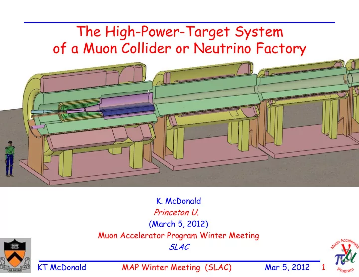
The High-Power-Target System
- f a Muon Collider or Neutrino Factory
- K. McDonald
Princeton U. (March 5, 2012) Muon Accelerator Program Winter Meeting SLAC
SLIDE 2
KT McDonald MAP Winter Meeting (SLAC) Mar 5, 2012 2
The Target is the Interface between a Proton Driver and or Beams
A Muon Collider is an energy-frontier particle-physics facility (that also produces lots of high-energy ’s). Higher mass of muon Better defined initial state than e+e- at high energy. A muon lives 1000 turns. Need lots of muons to have enough luminosity for physics. Need a production target that can survive multmegawatt proton beams.
SLIDE 3 KT McDonald MAP Winter Meeting (SLAC) Mar 5, 2012 3 R.B. Palmer (BNL, 1994) proposed a 20-T solenoidal capture system. Low-energy 's collected from side of long, thin cylindrical target. Solenoid coils can be some distance from proton beam. 10-year life against radiation damage at 4 MW. Liquid mercury jet target replaced every pulse. Proton beam readily tilted with respect to magnetic axis. Beam dump (mercury pool) out of the way of secondary 's and 's.
Target and Capture Topology: Solenoid
Desire 1014 /s from 1015 p/s ( 4 MW proton beam)
Present Target Concept:
Shielding of the superconducting magnets from radiation is a major issue. Magnet stored energy ~ 3 GJ!
Superconducting magnets Resistive magnets Proton beam and Mercury jet Be window Tungsten beads, He gas cooled Mercury collection pool With splash mitigator
5-T copper magnet insert; 15-T Nb3Sn coil + 5-T NbTi outsert. Desirable to replace the copper magnet by a 20-T HTC insert.
SLIDE 4 KT McDonald MAP Winter Meeting (SLAC) Mar 5, 2012 4 Power deposition in the superconducting magnets and the He-gas-cooled tungsten shield inside them, according to a FLUKA simulation. Approximately 2.4 MW must be dissipated in the shield. Some 800 kW flows out
into the downstream beam-transport elements. Total energy deposition in the target magnet string is ~ 1 kW @ 4k. Peak energy deposition is about 0.03 mW/g.
High Levels of Energy Deposition in the Target System
SLIDE 5 KT McDonald MAP Winter Meeting (SLAC) Mar 5, 2012 5
Large Cable-in-Conduit Superconducting Magnets
The high heat load of the target magnet requires Nb3Sn cable-in-conduit technology, more familiar in the fusion energy community than in high energy physics.
Incoloy Alloy 908 Conduit >1000 superconducting wires Supercritical helium flows in interstices and central channel
A high-temperature superconducting insert
- f 6+ T is appealing – but its inner radius
would also have to be large to permit shielding against radiation damage. The conductor is stabilized by copper, as the temperatures during conductor fabrication comes close to the melting point of aluminum. The conductor jacket is stainless steel, due to the high magnetic stresses.
SLIDE 6 KT McDonald MAP Winter Meeting (SLAC) Mar 5, 2012 6
The magnets at a Muon Collider and Neutrino Factory will be subject to high levels of radiation damage, and high thermal loads due to secondary particles, unless appropriately shielded. To design appropriate shielding it is helpful to have quantitative criteria as to maximum sustainable fluxes of secondary particles in magnet conductors, and as to the associated thermal load. We survey such criteria first for superconducting magnets, and then for room-temperature copper magnets. A recent review is by H. Weber, Int. J. Mod. Phys. 20 (2011),
http://puhep1.princeton.edu/~mcdonald/examples/magnets/weber_ijmpe_20_11.pdf Also, RESMM’12: https://indico.fnal.gov/conferenceDisplay.py?confId=4982
Most relevant radiation-damage data is from “reactor” neutrons (~ 1-10 MeV). Models of radiation damage to materials associate this with “displacement”
- f the electronic (not nuclear) structure of atoms, with a “defect” being induced by 25-100 eV of
deposited energy (although it takes only a few eV to displace an atom from a “lattice,” and defects can be produced by displacement of electrons from atoms without motion of the nucleus). Classic reference: G.H. Kinchin and R.S. Pease, Rep. Prog. Phys. 18, 1 (1955),
http://puhep1.princeton.edu/~mcdonald/examples/magnets/kinchin_rpp_18_1_55.pdf
“For displacement effects, a useful parameter is the total amount of energy imparted in displacing collisions.” –V.A.J. van Lint, The Physics of Radiation Damage in Particle Detectors, NIM A253, 453 (1987),
http://puhep1.princeton.edu/~mcdonald/examples/magnets/vanlint_nim_a253_453_87.pdf
Hence, it appears to me most straightforward to relate damage limits to (peak) energy deposition in
- materials. [In our case, use of DPA = displacements per atom is an unnecessary intermediate step, with
no simple relation between DPA and damage, http://www.hep.princeton.edu/~mcdonald/mumu/target/RESMM12/li.pdf ] Reactor-neutron radiation damage is closely equivalent to damage induced by high-energy cascades of the same local energy deposition (but not to that from, say, an 55Fe source).
Overview of Radiation Issues for the Solenoid Magnets
Si atom displaced with 50 keV
SLIDE 7 KT McDonald MAP Winter Meeting (SLAC) Mar 5, 2012 7
Radiation Damage to Superconductor
The ITER project quotes the lifetime radiation dose to the superconducting magnets as 1022 n/m2 for reactor neutrons with E > 0.1 MeV. This is also 107 Gray = 104 J/g accumulated energy deposition. For a lifetime of 10 “years” of 107 s each, the peak rate of energy deposition would be 104 J/g / 108 s = 10-4 W/g = 0.1 mW/g (= 1 MGray/year of 107 s). The ITER Design Requirements document, http://puhep1.princeton.edu/~mcdonald/examples/magnets/iter_fdr_DRG1.pdf reports this as 1 mW/cm3 of peak energy deposition (which seems to imply magnet 10 g/cm3). Damage to Nb-based superconductors appears to become significant at doses of 2-3 1022 n/m2 :
- A. Nishimura et al., Fusion Eng. & Design 84, 1425 (2009)
http://puhep1.princeton.edu/~mcdonald/examples/magnets/nishimura_fed_84_1425_09.pdf
Reviews of these considerations for ITER:
J.H. Schultz, IEEE Symp. Fusion Eng. 423 (2003)
http://puhep1.princeton.edu/~mcdonald/examples/magnets/schultz_ieeesfe_423_03.pdf http://puhep1.princeton.edu/~mcdonald/examples/magnets/schultz_cern_032205.pdf
Reduction of critical current of various Nb-based Conductors as a function of reactor neutron fluence. From Nishimura et al.
SLIDE 8 KT McDonald MAP Winter Meeting (SLAC) Mar 5, 2012 8
Radiation Damage to Organic Insulators
R&D on reactor neutron damage to organic insulators for conductors is carried out at the Atominstitut, U Vienna, http://www.ati.ac.at/ Recent review:
- R. Prokopec et al., Fusion Eng. & Design 85, 227 (2010)
http://puhep1.princeton.edu/~mcdonald/examples/magnets/prokopec_fed_85_227_10.pdf
The usual claim seems to be that “ordinary” expoy-based insulators have a useful lifetime of 1022 n/m2 for reactor neutrons with E > 0.1 MeV. This is, I believe, the underlying criterion for the ITER limit that we have recently adopted in the Target System Baseline,
http://puhep1.princeton.edu/~mcdonald/mumu/target/target_baseline_v3.pdf
Efforts towards a more rad hard epoxy insulation seem focused on cyanate ester (CE) resins, which are somewhat expensive (and toxic) . My impression is that use of this insulation brings about a factor
- f 2 improvement in useful lifetime, but see the cautionary summary of the 2nd link above.
Failure mode is loss of shear strength. Plot show ratio of shear strentgth (ILSS) To nominal for several CE resin variants at reactor neutron fluences of 1-5 1022 n/m2. From Prokopec et al.
SLIDE 9 KT McDonald MAP Winter Meeting (SLAC) Mar 5, 2012 9
Radiation Damage to the Stabilizer
Superconductors for use in high thermal load environments are fabricated as cable in conduit, with a significant amount of copper or aluminum stabilizer (to carry the current temporarily after a quench). The resistivity of Al is 1/3 that of Cu at 4K (if no radiation damage), Could be favorable to use Al. [Al not compatible with Nb3Sn conductor fabrication Must use Cu stabilize in high-field Nb magnets.] Radiation damage equivalent to 1021 n/m2 doubles the resistivity of Al and increases that of Cu by 10%.
http://puhep1.princeton.edu/~mcdonald/examples/magnets/klabunde_jnm_85-86_385_79.pdf
Annealing by cycling to room temperature gives essentially complete recovery of the low-temperature resistivity of Al, but only about 80% recovery for copper. Cycling copper-stabilized magnets to room temperature once a year would result in about 20% increase in the resistivity of copper stabilizer in the “hot spot” over 10 years; Al-stabilized magnets would have to be cycled to room temperature several times a year).
http://puhep1.princeton.edu/~mcdonald/examples/magnets/guinan_jnm_133_357_85.pdf
Hence, Cu stabilizer is preferred if want to operate near the ITER limit (and in high fields).
SLIDE 10 KT McDonald MAP Winter Meeting (SLAC) Mar 5, 2012 10
Radiation Damage to Inorganic Insulators
MgO and MgAl2O4 “mineral insulation” is often regarded as the best inorganic insulator for magnets. It seems to be considered that this material remains viable mechanically up to doses of 1026 n/m2 for reactor neutrons with E > 0.1 MeV., i.e., about 10,000 times that of the best organic insulators.
F.W. Clinard Jr et al., J. Nucl. Mat. 108-109, 655 (1982),
http://puhep1.princeton.edu/~mcdonald/examples/magnets/clinard_jnm_108-109_655_82.pdf
Question: Is the copper or SS jacket of a cable-in-conduit conductor with MgO insulation also viable at this dose? The main damage effect seems to be swelling of the MgO, which is not necessarily a problem for the powder insulation used in magnet conductors. PPPL archive of C. Neumeyer: http://www.pppl.gov/~neumeyer/ITER_IVC/References/
KEK may consider MgO-insulated magnets good only to 1011 Gray ~ 1026 n/m2.
http://www-ps.kek.jp/kekpsbcg/conf/nbi/02/radresmag_kusano.pdf
- A. Zeller advocates use of MgO-insulated superconductors, but it is not clear to me that this would permit significantly
higher doses due to limitations of the conductor itself.
SLIDE 11 KT McDonald MAP Winter Meeting (SLAC) Mar 5, 2012 11
Radiation Damage to Copper at Room Temperature
Embrittlement of copper due to radiation becomes significant at reactor neutrino doses > 1023 n/m2. Not clear if this is a problem for resistive copper magnets.
- N. Mokhov quotes limit of 1010 Gy = 100 mW/g for 10 “years” of 107 s each.
http://www-ap.fnal.gov/users/mokhov/papers/2006/Conf-06-244.pdf
Not discussed here, but shouldn’t be ignored altogether.
Radiation Damage to Shielding Material, Beam Pipes, Target, …
SLIDE 12
KT McDonald MAP Winter Meeting (SLAC) Mar 5, 2012 12
Production Solenoid Transport Solenoid Detector Solenoid
Production Target Collimators Stopping Target Tracker Calorimeter
COMET, Mu2e Target Solenoid Magnets
2.5T ~5T 2.0T 1.0T e
10-50 kW proton beam Collection of backward pions in a 5-T magnetic bottle. Limit field to 5 T so can use NbTi (and don’t have to use cable in conduit). Use existing ATLAS conductor with Al stabilizer. If operate this at ITER limit, must aneal at room temp 3 or more times a year. Or, use more shielding (COMET) to be at < 1/10 ITER limit.
SLIDE 13 KT McDonald MAP Winter Meeting (SLAC) Mar 5, 2012 13
Project X Targetry for a Neutral Kaon Beam and for Mu2e Upgrade
1 MW proton beam @ 3 GeV Search for K0
long 0
K0
long secondaries at 15-45
Small solid angle High-Z target favored Ga, Hg or PbBi “waterfall” could be optimal MARS simulations… Mu2e could upgrade to a 1-MW beam. Could use radiation-cooled carbon target as considered in Neutrino Factory Study 1.
- V. Lebedev advocates use of a rotating
cylinder of carbon to increase lifetime against radiation damage. However, a high-Z target is still favored, which could also be a liquid metal “waterfall”
SLIDE 14
KT McDonald MAP Winter Meeting (SLAC) Mar 5, 2012 14
Target Hall
Cost driver will be civil construction and shielding. LBNE 2-MW target station ~ $300m Crude sketch to start IDS-NF costing
NuMI target hall
SLIDE 15
KT McDonald MAP Winter Meeting (SLAC) Mar 5, 2012 15 Bz(at target) [T] Rtarget [cm] Bz(End of taper) [T] Rend of taper [cm] Nμ [104]
20 7.5 1.5 30 2.9 15 10 1.5 30 2.766
Do We Need 20 T?
It has been 14 years since Nikolai Mokhov studied the effect of varying the capture solenoid field. New BNL postdoc Hisham Sayed has started to review this. Ultimately can vary: 1. Peak field (nominally 20 T) 2. Aperture at target (nominally 7.5 cm) 3. Field in front end (nominally 1.5 T) 4. Aperture of front end (nominally 30 cm) 5. Length of “taper” from peak field to front-end field (nominally 15 m) First study only varied parameters at the target: Only 5% loss! We may be able to operate at 15 T peak field, and dispense with the resistive copper magnets!
SLIDE 16 KT McDonald MAP Winter Meeting (SLAC) Mar 5, 2012 16
Hardware Activities 1
MERIT Primary Containment Vessel Surface Inspection, Van Graves (ORNL) Use Zeiss Handysurf profilometer. Surface from vendor is mottled. Interior: Exterior: No evidence of pitting @ 20 µm
0.00 20.00 40.00 0.00 2.00 4.00 6.00 8.00 10.00 12.00 14.00
(µm) (mm)
Profile Curve
15.00 0.00 2.00 4.00 6.00 8.00 10.00 12.00 14.00
(µm) (mm)
Profile Curve
SLIDE 17
KT McDonald MAP Winter Meeting (SLAC) Mar 5, 2012 17
Hardware Activities 2
Autoradiography of MERIT beam windows, Peter Thieberger (BNL) σH = 4 mm, σV = 2.3 mm Autoradiograph of window on the Ti “pieplate “close to nozzle Horizontal, σ = 5 mm \ Vertical: σ = 3 mm
SLIDE 18
KT McDonald MAP Winter Meeting (SLAC) Mar 5, 2012 18
Targetry Presentations
Yan Zhan (Stony Brook) Nozzle and Jet Studies (towards improving the jet quality) Roman Samulyak (Stony Brook) MHD Simulations (including beam-jet interactions) Xiaoping Ding (UCLA) Particle-Production Simulations (including comparison of Ga with Hg) Nicholas Souchlas (PBL) Energy-Deposition Studies (to determine whether the superconducting magnets are sufficiently well shielded from the 4-MW beam power) Bob Weggel (MORE) Magnet and Shielding Configurations (now including gaps for services and supports)