THE EFFECT OF POST-PROCESSING OF CARBON FIBERS ON THE MECHANICAL - - PDF document

the effect of post processing of carbon fibers on the
SMART_READER_LITE
LIVE PREVIEW

THE EFFECT OF POST-PROCESSING OF CARBON FIBERS ON THE MECHANICAL - - PDF document

18 TH INTERNATIONAL CONFERENCE ON COMPOSITE MATERIALS THE EFFECT OF POST-PROCESSING OF CARBON FIBERS ON THE MECHANICAL PROPERTIES OF EPOXY-BASED COMPOSITES S.H. Han, H.C. Lee, Yong Sik Chung, S.S. Kim* Department of Organic Materials and Fiber


slide-1
SLIDE 1

18TH INTERNATIONAL CONFERENCE ON COMPOSITE MATERIALS

1 Introduction Carbon fiber reinforced composite materials have been widely used in the fields of aerospace as well as in the area of high technology products. To realize the excellent mechanical properties of carbon fiber in the composite, it is necessary to have a good interfacial adhesion between fiber and matrix to ensure effective load transfer from one fiber to another through the matrix. The interfacial behavior between the carbon fiber and matrix mainly depends

  • n the carbon fiber surface [1]. As the carbon fiber is

extremely inert, usually untreated carbon fiber composites exhibit a weak bonding between fiber and matrix, giving as result composites with relatively low interlaminar shear strength. This problem has been overcome to a large extent by the development of fiber surface treatments. The treatment of carbon fiber surface has been studied for a long time and several methods such as heat treatment [2], wet chemical or electrochemical

  • xidation [3-5], plasma treatment [6-8], gas-phase
  • xidation [9], and high-energy radiation technique

[10] have been demonstrated to be effective in the modification of the mechanical interfacial properties

  • f composites based on polar resins sucha s epoxy.

Other methods such as e.g., oxidative etching, polymer coating (sizing) or plasma activation, which improve the bond strength between the carbon fiber and the polymeric matrix [11-14]. Carbon fibers were surface-treated by acid as well as titanate coupling agent and characterized by SEM, tensile test. As-received and treated carbon fiber reinforced epoxy matrix composites were fabricated by hot-press molding method, and the mechanical properties of the composites were determined and

  • compared. The effects of the fiber surface on the

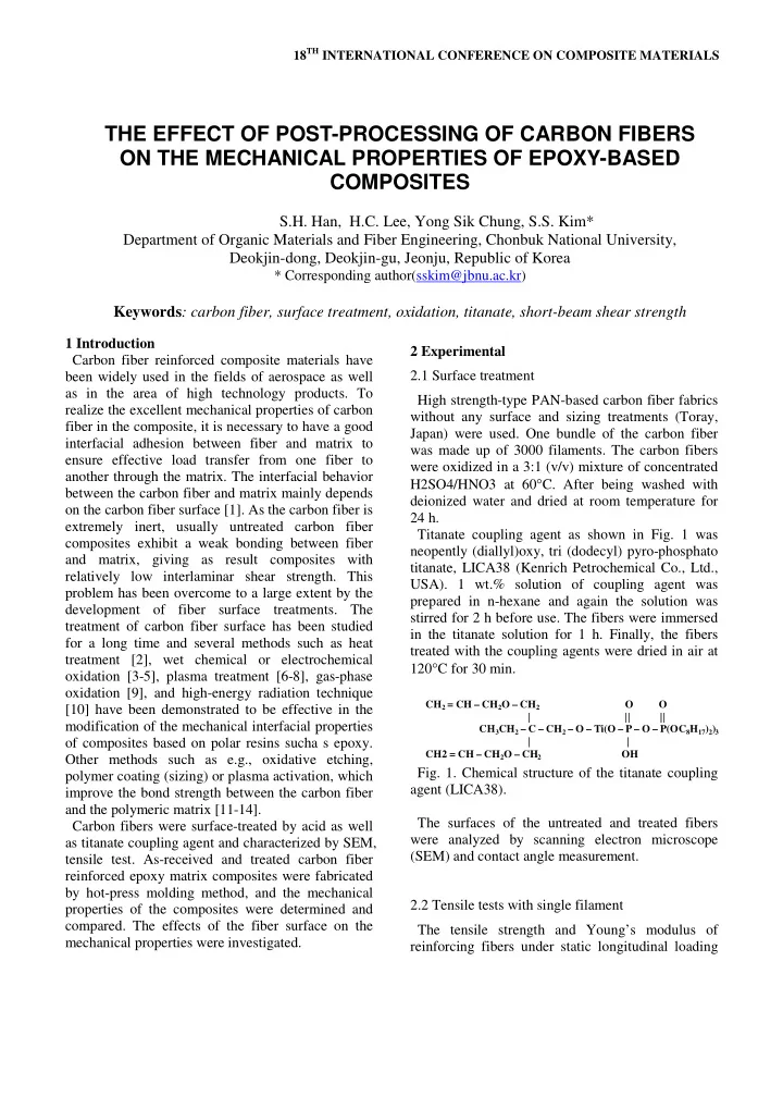
mechanical properties were investigated. 2 Experimental 2.1 Surface treatment High strength-type PAN-based carbon fiber fabrics without any surface and sizing treatments (Toray, Japan) were used. One bundle of the carbon fiber was made up of 3000 filaments. The carbon fibers were oxidized in a 3:1 (v/v) mixture of concentrated H2SO4/HNO3 at 60°C. After being washed with deionized water and dried at room temperature for 24 h. Titanate coupling agent as shown in Fig. 1 was neopently (diallyl)oxy, tri (dodecyl) pyro-phosphato titanate, LICA38 (Kenrich Petrochemical Co., Ltd., USA). 1 wt.% solution of coupling agent was prepared in n-hexane and again the solution was stirred for 2 h before use. The fibers were immersed in the titanate solution for 1 h. Finally, the fibers treated with the coupling agents were dried in air at 120°C for 30 min.

CH2 = CH – CH2O – CH2 O O | || || CH3CH2 – C – CH2 – O – Ti(O – P – O – P(OC8H17)2)3 | | CH2 = CH – CH2O – CH2 OH

  • Fig. 1. Chemical structure of the titanate coupling

agent (LICA38). The surfaces of the untreated and treated fibers were analyzed by scanning electron microscope (SEM) and contact angle measurement. 2.2 Tensile tests with single filament The tensile strength and Young’s modulus of reinforcing fibers under static longitudinal loading

THE EFFECT OF POST-PROCESSING OF CARBON FIBERS ON THE MECHANICAL PROPERTIES OF EPOXY-BASED COMPOSITES

S.H. Han, H.C. Lee, Yong Sik Chung, S.S. Kim* Department of Organic Materials and Fiber Engineering, Chonbuk National University, Deokjin-dong, Deokjin-gu, Jeonju, Republic of Korea

* Corresponding author(sskim@jbnu.ac.kr)

Keywords: carbon fiber, surface treatment, oxidation, titanate, short-beam shear strength

slide-2
SLIDE 2

were determined based on the ASTM D 3379-75 standard test method for single filament materials. As show in Fig. 2, the fiber specimen was adhesively bonded to a thin paper which has a central longitudinal slot of fixed gage length. Epoxy resin to fix the filament was extended to the longitudinal direction to relieve stress concentration

  • n the fixed part when the filament was out of
  • alignment. Once the specimen is clamped in the

grips of the tensile testing machine, the backing strip was cut away, so that the filament transmits all the applied tensile load. The specimen was pulled to failure, the load and elongation were recorded, and the tensile strength and modulus were calculated from the usual formulas.

25 20 60 Carbon filament Epoxy Grip area Thin paper Carbon filament Epoxy

  • Fig. 2. Single filament tensile test specimen.

2.3 Short beam shear test with the composites A common approach to estimate the interfacial strength between fiber and matrix is to use the single-fiber test. Many types of single-fiber tests exist, all of which require loading a single fiber while it is encapsulated in matrix material. But the test results tend to be qualitative rather than quantitative, often showing considerable data scatter. An alternative is to test an actual composite. A short beam shear test of the composite can be performed. The carbon fiber fabric reinforced epoxy composites were made using both untreated and treated carbon fibers. The epoxy resin was a bisphenol-A/F type liquid one with aliphatic glycidyl ether, YD-114F (KUKDO Chemical Co., Ltd., Korea). Curing was performed in a compression moulding machine, and the curing process was involved heating at 80°C for 2h. During the curing process, the pressure was 0.6 MPa which was loaded after the temperature being increased to 80°C. When the curing process had finished, the mould was cooled to room temperature with the pressure being maintained. The interlaminar shear strength (ILSS) of the CF/Epoxy composites were measured on a universal testing machine (INSTRON 4469, MA, USA) using a three point short beam bending test method according to ASTM D2344. Specimen dimensions were 24 mm · 6.5 mm· 4 mm, with a span to thickness ratio

  • f

6. The specimens were conditioned and an enclosed space where the test was conducted was maintained at room temperature. The specimens were measured at a rate of cross- head movement of 1 mm/min. The ILSS, τ, for the short-beam test was calculated according to the following Eq. (1):

bh P

R

4 3 = τ

(1) where PR is the maximum compression force at fracture in Newtons, b is the width of the specimen in mm, and h is the thickness of the specimen in mm. Each ILSS value was the average of more than five successful measurements. 3 Results and discussion

  • Fig. 3 shows the contact angle measurement with

respect to the oxidation treatment time. The contact angles were measured at three different points on each specimen and average values were calculated. There was no significant change on the contact angle until 2 hours treatment, but it dropped sharply after 3

  • hours. This means there might be notable changes in

the carbon fiber surface. The surfaces of specimens were examined by SEM, in order to determine whether changes caused by the

  • xidation could be distinguished as shown in Fig. 4.
slide-3
SLIDE 3

3 PAPER TITLE

(a) (b) (c) (d)

  • Fig. 3. Contact angle measurement w.r.t. oxidation

treatment time; (a) untreated, (b) 1h, (c) 2h, (d) 3h. The surface of untreated carbon fiber was smooth and few shallow grooves that were parallel distributed along with logintudinal direction of the fiber appeared as shown in Fig. 4(a). The number of shallow grooves became increased as the treatment time increased. (a) (b) (c) (d)

  • Fig. 4. SEM topographies of carbon fiber with

respect to oxidation treatment time; (a) untreated, (b) 1h, (c) 2h, (d) 3h. There were many deep grooves and damages on the surface of carbon fiber after 3h oxidation treatment as shown in Fig. 4(d).

3.56 3.64 3.38 1.95 1 2 3 4 5 1 2 3 4 5 Tensile strength (GPa) Untreated 1 h 2 h 3 h

  • Fig. 5. Tensile strength of carbon fibers with respect

to oxidation treatment time. This significant change on the surface caused the rapid decrease in contact angle. The sudden transition of surface reduced the tensile strength of carbon fiber by 45.3% compared to that of untreated

  • ne as shown in Fig. 5.
  • Fig. 6 shows the surfaces of specimens examined

by SEM, in order to determine whether changes caused by the titanate coupling agent could be distinguished. (a) (b) (c) (d) 39.4° 41.8° 40.4° 29.5°

slide-4
SLIDE 4

(e) (f)

  • Fig. 6. SEM topographies of carbon fiber with

respect to the titanate concentration and oxidation treatment time; (a) 0.2wt%, (b) 1.0wt%, (c) 3.0 wt%, (d) 1h+1wt%, (e) 2h+1wt%, (f) 3h+1wt%. In case of the specimen treated with 0.2wt% titanate, no significant change was observed on the surface. From 1.0wt% concentration, some nubbles were found on the surface of the specimen. The oxidation treated specimen before titanate coating, however, showed smooth surface and most small deep grooves generated by oxidation treatment shown in Fig. 4(d) were disappeared as shown in Fig. 6(f).

3.64 3.85 4.08 1 2 3 4 5 0.5 1 1.5 2 2.5 3 3.5 Tensile strength (GPa) 0.2wt% 1.0wt% 3.0wt%

(a)

3.67 3.72 3.51 1 2 3 4 5 0.5 1 1.5 2 2.5 3 3.5 Tensile strength (GPa) 1 h 2 h 3 h

(b)

  • Fig. 7. Tensile strength of carbon fibers with respect

to surface treatment; (a) titante concentration without oxidation, (b) oxidation time with 1wt% titante concentration.

  • Fig. 7 shows the tensile strength of carbon fibers

with respect to the titanate concentration and

  • xidation treatment time. The tensile strength of the

specimen treated with 3.0wt% titante increased by 14.6% compared to that of the untreated specimen as shown in Fig. 7(a), because grains or pores on the fiber surface could be filled with titanate. When the specimen was treated with titanate after oxidation, the decrease in tensile strength was moderated as shown in Fig. 7(b). From these results, it was found that the titanate treatment was effective against fiber surface damage.

22.19 14.50 18.88 19.02 5 10 15 20 25

1 2 3 4 5

Short-beam strength (MPa) Untreated Oxidation O Titanate X Oxidation X Titanate O Oxidation O Titanate O

  • Fig. 8. Short-beam strength of the carbon/epoxy

composite specimens with respect to surface treatment on the carbon fiber. Short-beam shear test results with the carbon fabric/epoxy composites were shown in Fig 8. Strength of the specimen made of oxidation-treated carbon fibers decreased by 34.7% compared to that

  • f untreated specimen. This phenomenon shows that

the property degradation of carbon fiber is more dominant than the rough surface on the strength of composite materials. Strength of oxidation-treated carbon fiber composite specimen increased 31.2% when the titanate treatment was followed after

  • xidation. However, interaction between titanate
slide-5
SLIDE 5

5 PAPER TITLE

coupling agent and epoxy resin was not effective in enhancing the shear strength of the composite materials. (a) (b) (c) (d)

  • Fig. 9. Cross-sectional surface of the short-beam

shear specimen with respect to fiber surface treatment; (a) untreated, (b) oxidation treatment, (c) titanate treatemtn, (d) titante treatment after

  • xidation.
  • Fig. 9 shows the microscopic images of specimen’s

cutting surface. At the specimens whose fiber was treated with oxidation and titanate, large amount of void was observed compared to the untreated

  • specimen. The relatively large void contents caused

the low shear strength of the specimen. Accordingly, additional future work to reduce void volume content will be followed. 4 Conclusions

Carbon fibers were surface-treated by acid as well

as titanate coupling agent and characterized by SEM, tensile test. As-received and treated carbon fiber reinforced epoxy matrix composites were fabricated by hot-press molding method, and the mechanical properties of the composites were determined and

  • compared. The following conclusions can be drawn

from the present investigations: (1) Oxidation treatment for 3 hours reduced the tensile strength of carbon fiber by 45.3% compared to that of untreated one. (2) Tensile strength of the specimen treated with 3.0wt% titante increased by 14.6% compared to that of the untreated specimen due to the pores filling effect. (3) When the carbon fiber was treated with titanate after oxidation, the decrease in tensile strength was moderated. (4) Strength of the composite specimen made of

  • xidation-treated carbon fibers decreased by

34.7% compared to that of untreated one due to fiber damage. (5) Titanate coupling agent was not effective in enhancing the shear strength of the composite materials due to large void content. References

[1] J.S. Lee, T.J. Kang, “Changes in physic-

chemical and morphological properties of carbon fiber by surface treatment”. Carbon, Vol. 35, No. 2, pp 209-216, 1997.

[2] A. Bismarck, C. Wuertz, J. Springer, “Basic

surface oxides on carbon fibers”, Carbon, Vol. 37, pp 735-741, 2002.

[3] Z.R. Yue, W. Jiang, L. Wang, S.D. Gardner,

C.U. Pittman Jr, “Surface characterization of electrochemically

  • xidized

carbon fibers”, Carbon, Vol. 37, pp 1785-1796, 1999.

[4] A. Fukunaga, S. Ueda, M. Nagumo, “Air-

  • xidation and anodization of pitch-based carbon

fibers”, Carbon, Vol. 37, pp 1081-1085, 1999.

[5] S. Febo, F. Leonardo, P. Mario, P. Luca,

“Chemical modification of carbon fibres surfaces”, Carbon, Vol. 40, pp 735-741, 2002.

[6] M.A.

Montes-Moran, A. Martinez-Alonso, J.M.D. Tascon, R.J. Young, “Effect of plasma

  • xidation on the surface and interfacial

properties of ultra-high modulus carbon fibres”, Composites, Vol. 32, pp 361-371, 2001.

[7] N. Dilsiz, N.K. Erinc, E. Bayramli, G. Akovali,

“Surface energy and mechanical properties of plasma-modified carbon fibres”, Carbon, Vol. 33, pp 853-858, 1995.

[8] M.A. Montes-Moran, F.W.J. Van Hattum, J.P.

Nunes, A. Martinez-Alonso, J.M.D. Tascon, C.A. Bernardo, “A study of the effect of plasma

slide-6
SLIDE 6

treatment on the interfacial properties of carbon fibre-thermoplastic composites”, Carbon, Vol. 43, pp 1778-1814, 2005.

[9] C. Xu, F. Mark, Y. Gao, K. Indrek, M. Suuberg

Eric, H. Hurt, “Mechanisms of surfactant adsorption on non-polar, air-oxydized and

  • zone-treated carbon surfaces”, Carbon, Vol. 41,

pp 1489-1450, 2003.

[10] J. Li, Y. Huang, Z. Xu, Z. Wang, “High-energy

radiation technique treat on the surface of carbon fiber”, Mater Chem Phys, Vol. 94, pp 315-321, 2005.

[11] J.B.

Donnet, G. Gilpain, “Suface characterization of carbon fibres”. Compoistes,

  • Vol. 13, No. 3, pp 207-212, 1992.

[12] D. Upadhyaya, P. Tsahiropoulos, “Evaluation of

the effect of sizing levels on transverse flexural and shear strengths of carbon/epoxy composites”. J Mater Process Technol, Vol. 54, pp 17-20, 1995.

[13] L.T.

Drzal, M. Madhukar, “Fiber-matrix adhesion and its relationship to composite mechanical properties”. J Mater Sci, Vol. 28, pp 569-610, 1993.

[14] J.F. Timmerman, B.S. Hayes, J.C. Seferis,

“Cryogenic microcracking of carbon fiber/epoxy composites: Influences of fiber-matrix adhesion”, J Comp Mater, Vol. 37, pp 1939-1950, 2003.