THE BIGGEST LITTLE ANTENNA IN THE WORLD Ed Kardjala The Navys VLF - - PowerPoint PPT Presentation

the biggest little antenna in the world
SMART_READER_LITE
LIVE PREVIEW

THE BIGGEST LITTLE ANTENNA IN THE WORLD Ed Kardjala The Navys VLF - - PowerPoint PPT Presentation

THE BIGGEST LITTLE ANTENNA IN THE WORLD Ed Kardjala The Navys VLF antenna at Cutler Maine Edward M. Newman AP-S Nov. 14, 2012 A small SMALL ANTENNA CUTLER VLF (3-30 KHz) ANTENNA Why A VLF Antenna? Types


slide-1
SLIDE 1

THE BIGGEST LITTLE ANTENNA IN THE WORLD

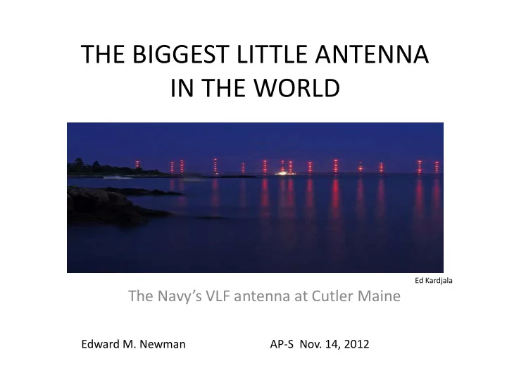
The Navy’s VLF antenna at Cutler Maine

Edward M. Newman AP-S Nov. 14, 2012

Ed Kardjala

slide-2
SLIDE 2

A small SMALL ANTENNA

slide-3
SLIDE 3

CUTLER VLF (3-30 KHz) ANTENNA

  • Why A VLF Antenna?
  • Types Of Antennas
  • Trideco Design At Cutler, Me.
  • Towers and Top Load
  • Tuning Network
  • Ground System
  • Deicing
  • Modulation and Reception
slide-4
SLIDE 4

HISTORICAL VLF ANTENNAS

  • Marconi transmitter

at Poldhu, UK

  • Height: 200 ft.
  • Built 1900
  • Destroyed by Storm

1901

  • 24 KW
  • 80 KHz
  • Telefunken Transmitter

at Sayville

  • Height: 477 ft.
  • Built 1912
  • 200 KW
  • 32 KHz
  • German WW II VLF

Antenna (Goliath)

  • Height: 673 ft.
  • Removed by Soviets

After the War

  • 1800 KW
  • 16 KHz
slide-5
SLIDE 5

“ka” MEASURE OF ANTENNA ELECTRICAL SIZE

Wave Number = k = 2π/λ Wavelength = λ Radianlength = λ/2π = 1/k a = radius of sphere (Chu Sphere) that circumscribes antenna ka = 1/2 largest antenna dimension in Radianlengths Electrically small antenna = ka<0.5 FOR CUTLER ANTENNA Frequency = 15 KHz H/λ = 140/20,000 = .007 λ = 20 Km Effective Height = H = 140 m a/λ = 640/20000 = .032 Physical Radius = RP = 625 m a = SQRT(RP

2 + H2) = 640 m

ka = 2πa/λ = 0.20

slide-6
SLIDE 6

0.25 0.5 0.75 1 1.25 1.5 1.75 2 0.1 1 10 100 1 .103 ka (Radianlength) Q

.

Q LIMITS FOR SMALL ANTENNAS

Cutler f = 24 KHz ka = 0.32 No Loss, Q = 259 74.9% Rad Eff, Q = 194 Chu-Hansen Limit Single Spherical Mode ka ≤ π/2, 2a ≤ λ/2 Wheeler Limit Lumped Element ka ≤ 1/2, 2a ≤ λ/2π Wheeler lower bound for Q Chu lower bound for Q

( ) ( )

3 2 LB

ka ka 1 Q + =

( )

3 LB

ka 1 Q =

  • A. R. Lopez
slide-7
SLIDE 7

WHY A VLF SYSTEM?

  • With the creation of ballistic missile submarines it

became essential to maintain communications

  • To avoid detection, nuclear submarines must remain

submerged

  • VLF provided penetration of seawater 30 to 100 feet

because of the very long wavelength

  • Very low loss propagation (2 dB/1000 Km)
slide-8
SLIDE 8

BALLISTIC MISSILE SUBMARINES

  • USS NAUTILUS
  • FIRST NUCLEAR-POWERED SUB
  • COMMISSIONED 1954
  • OPERATE SUBMERGED FOR MONTHS
  • USS GEORGE WASHINGTON
  • FIRST BALLISTIC MISSILE SUB
  • 16 POLARIS MISSILES
  • COMMISSIONED DEC 1959
slide-9
SLIDE 9

SKIN DEPTH

slide-10
SLIDE 10

US NAVY VLF COMMUNICATION SYSTEM (1990s)

slide-11
SLIDE 11

VLF ANTENNA SYSTEM REQUIREMENTS (1959)

  • Tunable 14.3-30 KHz
  • Radiated power: 1 MW
  • Max voltage: 200KV; Max E-field: 0.65 KV/mm
  • Efficiency: >50% ($500K penalty)
  • Bandwidth: at least 30 Hz
  • Operational conditions include 1 1/2-inch ice and 175-

MPH winds

  • Redundant for reliability and maintenance- two antennas
slide-12
SLIDE 12

ANTENNA CONFIGURATIONS

TRIATIC TOP LOAD UMBRELLA TOP LOAD TRIDECO TOP LOAD

slide-13
SLIDE 13

EXAMPLE OF TRIATIC

RCA’s Radio Central at Rocky Point Used A Set Of Triatic Antennas

slide-14
SLIDE 14

WHEELER ELECTRICAL DESIGN

Ref 1

Assumptions f = 15 KHz lambda = 20,000 m p = power factor = .002 P = 1 Megawatt A = effective area h = effective height Ah = effective volume V = max. topload voltage = 200 KV Ea = maximum E-field gradient on topload = .65 KV/mm Aa = conductor area

Derived a few simple formulas which define the gross antenna dimensions

  • 3. Effective height = .608/3.02 = 200 m. (140m)
slide-15
SLIDE 15

WIPL-D Model (Radius = 625 m, Height = 140 m)

Wire Dia. = 2 m Shunt Inductance (29.3 μH) Series Inductance (142 μH) Generator

  • A. R. Lopez
slide-16
SLIDE 16

Computed Reflection (Impedance)

OC SC J1.00

  • j1.00

Radiation Efficiency = 100% f = 24 KHz Q = 259 Note: Q computed using Yaghjian-Best Formula: AP Trans., Apr 2005

X and R for increment Frequency f frequency sonant Re f f / f X X R R 2 f / f Q

2 2

∆ ∆ = ∆ =         ∆ + ∆ + ∆ ∆ =

  • A. R. Lopez
slide-17
SLIDE 17

TRIDECO ANTENNA

  • Six topload panels
  • 13 towers
  • Approx. 1000 Acres
  • Minimizes Corona
slide-18
SLIDE 18

TWO ANTENNAS OCCUPY 2000 ACRES ON A PENNINSULA

  • Dual transmitter feeds helix

house through 100 ohm coax

  • Helix house contains tuner
  • Trideco top load uses 6 panels

for each monopole

Ref 6

slide-19
SLIDE 19

OVERVIEW OF ANTENNA CONFIGURATION

Location, location

Google Maps Ref 7

slide-20
SLIDE 20

26 TOWERS- 850 to 1000 FT HIGH

Ref 8

slide-21
SLIDE 21

SATELLITE IMAGES

Power Plant 18 MW Main Tower And Helix House

Bing Maps

slide-22
SLIDE 22

EACH ANTENNA CONSISTS OF 13 TOWERS

Exciting Engineering Work

Ref 8

slide-23
SLIDE 23

TOPLOAD FEED SYSTEM

Ref 7

slide-24
SLIDE 24

ANTENNA PERFORMANCE (24 KHz)

Ref 7

slide-25
SLIDE 25

CUTLER PERFORMANCE VS FREQUENCY

Ref 2

slide-26
SLIDE 26

DESIGN ISSUES

  • Corona/Lightning
  • Mechanical Design
  • Ice Load
  • Antenna Impedance and Efficiency
  • Ground system
  • Transmitter
slide-27
SLIDE 27

DESIGN ISSUE: CORONA

  • Actual Antenna Voltages

250 KV Plus Lightning

  • Electrical Breakdown of

the Air

  • Depends on Field

Strength, Geometry and Air Pressure

  • Designed in 1959 for

Cutler Antenna using model and 50 KV

  • Special hollow 1.5in cable

used in critical areas

slide-28
SLIDE 28

TOPLOAD PANEL CONSTRUCTION

  • 24,000 feet of cable – 120,000 pounds
  • Wire spacing optimized for equal charge
  • Wire diameter selected to meet specified electric field (0.65-0.8

KV/mm)

Ref 6

slide-29
SLIDE 29

FEED LINES AND INSULATORS

slide-30
SLIDE 30

EACH INSULATOR IS 57 FT LONG TO WITHSTAND 250 KV

13,000 lbs.

Ref 4

slide-31
SLIDE 31

TOPLOAD COUNTERWEIGHT SYSTEM

slide-32
SLIDE 32

TOPLOAD COUNTERWEIGHT SYSTEM

  • Counterweights weight

220 Tons

  • Panels can move with

wind and ice load

  • Panels can be lowered

for maintenance

  • Pulley system reduces

weight movement

Ref 5

slide-33
SLIDE 33

TOPLOAD COUNTERWEIGHT SYSTEM

Concrete filled wheel

Ref R. Mohn

slide-34
SLIDE 34

TOPLOAD DEICING

DEICING POWER

  • Deice one antenna at a time
  • Topload designed to be lossy at 60 Hz
  • 1.6 W/Sq. In =7.5 Megawatts to Deice
  • Diesel generators provide 18 Mw

Ref 7

slide-35
SLIDE 35

TUNING NETWORK-HELIX HOUSE

slide-36
SLIDE 36

TUNING NETWORK

  • Handle 200 KV And 2000

Amps

  • Very Low Loss <<0.1 Ohm
  • Tune Antenna Over 14-28

KHz

  • Tune Antenna with

Modulation

  • Antenna Impedance is

Capacitive

Ref 7

slide-37
SLIDE 37

TUNING NETWORK- HELIX

Ref 8

slide-38
SLIDE 38

TUNING NETWORK- HELIX

slide-39
SLIDE 39

TUNING NETWORK-VARIOMETER

Wires are 4 inches diameter NSS

NAA

Ref 5 JP Hawkins

slide-40
SLIDE 40

TUNING HELIX -LITZ WIRE

JP Hawkins

slide-41
SLIDE 41

TUNING HELIX- LITZ WIRE

  • Critical to reducing loss in

high power tuning inductors

  • Skin effect forces most AC

current to the surface of a solid conductor, increasing resistance

  • Litz wire equalizes current

throughout a large conductor

  • Thousands of small wires

are insulated, braided and packed in large conductor

  • Cutler design is a Litz

conductor 4 inches in diameter, with 3 parallel conductors

Ref 9

slide-42
SLIDE 42

TUNING INDUCTOR IN HELIX HOUSE

Ref 5

slide-43
SLIDE 43

TUNING NETWORK- TRANSMITTER OUTPUT TRANSFORMER

NAA NSS

Ref 5 JP Hawkins

slide-44
SLIDE 44

COAXIAL FEED LINE- TRANSMITTER TO HELIX HOUSE

  • 100 Ohm Feed Line From

Transmitter To Helix House

  • 1MW Power Capacity
  • 100 KV
  • 2000 Amps

Ref 5

slide-45
SLIDE 45

DESIGN ISSUE: GROUND SYSTEM LOSS

2000 Miles of #6 Copper Wire Cover the Peninsula and Run Into the Sea

Ref 5

slide-46
SLIDE 46

CUTLER GROUND SYSTEM PERFORMANCE

Ref 2

slide-47
SLIDE 47

DUAL TRANSMITTERS: 1MW EACH

slide-48
SLIDE 48

TRANSMITTERS

slide-49
SLIDE 49

DATA/MODULATION

FREQ SHIFT KEYING MINIMUM SHIFT KEYING

slide-50
SLIDE 50

MODULATION

  • Narrowband MSK (50-200 bps)
  • Continuous Modulation
  • Encrypted
  • Antenna reactor tunes with

modulation

slide-51
SLIDE 51

SUBMARINE RADIO RECEIVERS

USS Nautilus 1970s USS Robert E Lee 1966

slide-52
SLIDE 52

MODERN VLF RECEIVER

  • UP TO FOUR 50 BPS

CHANNELS

  • MULTIPLEXED,

ENCRYPT AND ENCODE

  • MSK MODULATION
slide-53
SLIDE 53

ACKNOWLEDGEMENTS

My thanks to Al Lopez, Peder Hansen, Nick England and Harold Wheeler for their invaluable contributions.

slide-54
SLIDE 54

REFERENCES

  • 1. H.A. Wheeler, “Fundamental Relations in the Design of a VLF Transmitting Antenna” IRE Trans. AP, vol AP-6,

January 1958, pp 120-122

  • 2. Watt, A. D., “VLF Radio Engineering”, Elmsford, N.Y., Pergamon Press, 1967
  • 3. Peder Hansen, Doeg Rodriguez, “High Power VLF/LF Transmitting Antennas- Wheeler’s Circuit Approximations

Applied to Power Limitations, IEEE AP-S Symposium, 2012

  • 4. Jim Holmes, “New Insulators Keep Antenna System Up & Running, SPAWAR Bulletin
  • 5. M. Mann, “Navy Builds Worlds Most Powerful transmitter”, Popular Science, pp 60-63, Sept. 1960
  • 6. P. Hansen, R. Olsen “VLF Cutler Hollow core cable Repair Replacement” Technical Report 1681, Sept. 1994
  • 7. P. Hansen, J. Chavez, VLF Cutler: Four-Panel tests; RADHAZARD Field Strength Measurement, Tech Report 1761,

Jan 1998

  • 8. P. Hansen, “US Navy FVLF/LF Transmitters- Large electrically Small Antennas”, SS-PAC San Diego SDSU Feb. 2010
  • 9. Jasik& Johnson, “Antenna Engineering Handbook, 2nd edition” McGraw-Hill Book Co. 1961

Chapter 6 H. A. Wheeler; Chapter 24 B. G. Hagaman

  • 10. NAVELEX MANUAL 0101,113 “VLF Communication Equipment”
  • 11. navy-radio.com

12.

  • H. A. Wheeler Design Notes ARLAssociates.com
slide-55
SLIDE 55

HISTORICAL NOTES:SAYVILLE DESIGN INFORMATION- 1918

slide-56
SLIDE 56

HISTORICAL NOTES: RADIO CENTRAL TUNING NETWORK

slide-57
SLIDE 57

HISTORICAL NOTES: RADIO CENTRAL TRANSMITTER