
SLIDE 1
Test Results: Working Fluids Tests
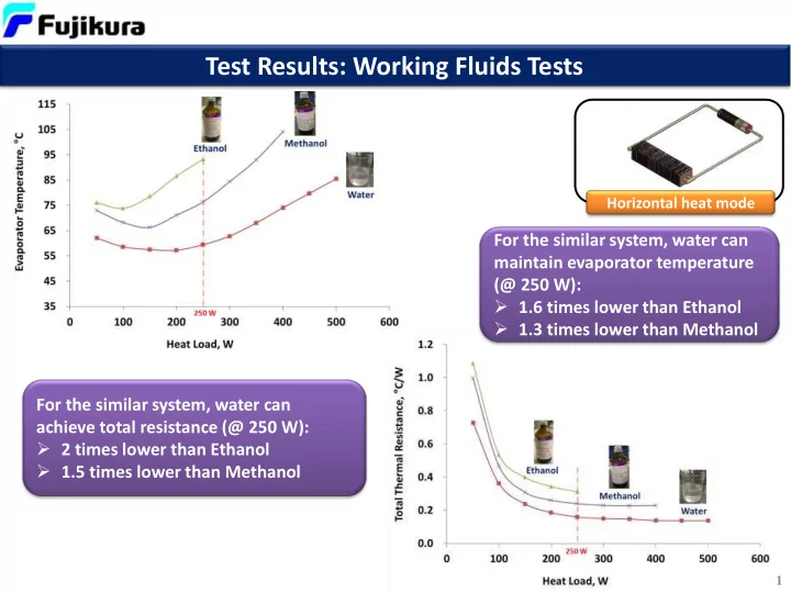
Horizontal heat mode
For the similar system, water can maintain evaporator temperature (@ 250 W):
- 1.6 times lower than Ethanol
- 1.3 times lower than Methanol
For the similar system, water can achieve total resistance (@ 250 W):
- 2 times lower than Ethanol
- 1.5 times lower than Methanol
1