
SLIDE 1
18TH INTERNATIONAL CONFERENCE ON COMPOSITE MATERIALS
1 Introduction The tapping test has the ability indicating damage in a structural element due to a localized change of stiffness [1]. The change in vibration signature may be detected by ear or more precisely by measurement instrumentation. In this paper, a tapping test method for discriminating between measurements made on undamaged and delaminated structures is presented. It has been shown that the characteristics of radiated sound from a structure during a tapping are changed by the presence of damage in composite laminate. For structurally radiated sound, the sound field is directly coupled to the structural motion. Therefore, Impact response analysis should be performed. In this study, the radiated sound induced by tapping is computed by solving the Rayleigh integral equation. And the delamination model is used to analyze the impact response analysis of delaminated composite laminate. Predicted impact force histories and sound pressure histories are compared with tapping test data. The results of tests and analyses are presented and it is concluded that the impact force and acoustic pressure data can be used to identify the presence of
- delamination. And it is shown that the presented
analysis model was found to be reliable for predicting the tapping phenomena. 2 Impact response analyses 2.1 Spring-mass model Spring-mass models are simple and provide accurate
- solutions. The most complete model consists of one
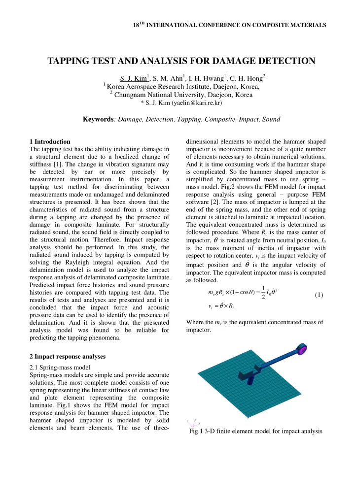
spring representing the linear stiffness of contact law and plate element representing the composite
- laminate. Fig.1 shows the FEM model for impact
response analysis for hammer shaped impactor. The hammer shaped impactor is modeled by solid elements and beam elements. The use of three- dimensional elements to model the hammer shaped impactor is inconvenient because of a quite number
- f elements necessary to obtain numerical solutions.
And it is time consuming work if the hammer shape is complicated. So the hammer shaped impactor is simplified by concentrated mass to use spring – mass model. Fig.2 shows the FEM model for impact response analysis using general – purpose FEM software [2]. The mass of impactor is lumped at the end of the spring mass, and the other end of spring element is attached to laminate at impacted location. The equivalent concentrated mass is determined as followed procedure. Where Rc is the mass center of impactor, θ is rotated angle from neutral position, I0 is the mass moment of inertia of impactor with respect to rotation center, vi is the impact velocity of impact position and θ
is the angular velocity of
- impactor. The equivalent impactor mass is computed
as followed.
i i c e
R v I gR m × = = − × θ θ θ
- 2
2 1 ) cos 1 (
(1)
Where the me is the equivalent concentrated mass of impactor. Fig.1 3-D finite element model for impact analysis
TAPPING TEST AND ANALYSIS FOR DAMAGE DETECTION
- S. J. Kim1, S. M. Ahn1, I. H. Hwang1, C. H. Hong2
1 Korea Aerospace Research Institute, Daejeon, Korea, 2 Chungnam National University, Daejeon, Korea