T HE high luminosity LHC upgrade aims at increasing the integrated - - PDF document

t
SMART_READER_LITE
LIVE PREVIEW

T HE high luminosity LHC upgrade aims at increasing the integrated - - PDF document

This article has been accepted for publication in a future issue of this journal, but has not been fully edited. Content may change prior to final publication. Citation information: DOI 10.1109/TASC.2017.2651358, IEEE Transactions on Applied


slide-1
SLIDE 1

1051-8223 (c) 2016 IEEE. Personal use is permitted, but republication/redistribution requires IEEE permission. See http://www.ieee.org/publications_standards/publications/rights/index.html for more information. This article has been accepted for publication in a future issue of this journal, but has not been fully edited. Content may change prior to final publication. Citation information: DOI 10.1109/TASC.2017.2651358, IEEE Transactions on Applied Superconductivity

2LPo2B-09 1

Magnetic Analysis of the Nb3Sn low-beta Quadrupole for the High Luminosity LHC

  • S. Izquierdo Bermudez, G. Ambrosio, G. Chlachidze, P. Ferracin, E. Holik, J. Di Marco, E. Todesco, G.L. Sabbi, G. Vallone,
  • X. Wang.

Abstract— As part of the Large Hadron Collider Luminosity

upgrade (HiLumi-LHC) program, the US LARP collaboration and CERN are working together to design and build 150 mm aperture Nb3Sn quadrupoles for the LHC interaction regions. A first series of 1.5 m long coils were fabricated, assembled and tested in the first short model. This paper presents the magnetic analysis, comparing magnetic field measurements with the expectations and the field quality requirements. The analysis is focused on the geometrical harmonics, iron saturation effect and cold-warm correlation. Three dimensional effects such as the variability of the field harmonics along the magnet axis and the contribution of the coil ends are also discussed. Moreover, we present the influence of the conductor magnetization and the dynamic effects.  Index Terms— High Luminosity LHC, Field Quality, Magnetic Measurements, High Field Nb3Sn Magnet.

  • I. INTRODUCTION

HE high luminosity LHC upgrade aims at increasing the

integrated luminosity of the LHC by a factor of 10 beyond its nominal performance expected for 2023 [1]. Part of the upgrade relies on the replacement of the single aperture quadrupoles in the interaction region (the so called low-β or inner triplet quadrupoles). The design, referred as MQXF, foresees a 150 mm aperture quadrupole based on Nb3Sn technology [2]. The first MQXF short model (MQXFS1a) has been assembled in LBNL [4] and tested at FNAL [5], using two coils produced by LARP (coils 3 and 5) and two coils produced by CERN (coils 103 and 104). The four coils are made using OST Restacked-Rod-Process (RRP) Nb3Sn wires, using 108/127 stack for LARP coils and 132/169 stack for CERN

  • coils. This paper presents the results and analysis of the

magnetic measurements performed on MQXFS1a.

  • II. MAGNET DESIGN

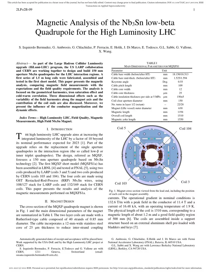
The cross-section of the MQXF quadrupole magnet is shown in Fig. 1 and the main dimensional parameters of the magnet are summarized in Table I. The two layer coils are made with a Rutherford-type cable composed of 40 strands of 0.85 mm

  • diameter. The cable incorporates a 12-mm-wide stainless steel

core of 25 μm thickness to reduce inter-strand coupling

Automatically generated dates of receipt and acceptance will be placed here; Work supported by the USA-DoE and by the High Luminosity LHC project at CERN.

  • S. Izquierdo Bermudez, P. Ferracin, E.Todesco and G. Vallone are with

CERN, 1211 Geneva, Switzerland (email: susana.izquierdo.bermudez@cern.ch).

  • currents. The operational gradient in nominal conditions is

132.6 T/m with a peak field in the conductor of 11.4 T and a current of 16.48 kA, with an operating temperature of 1.9 K. The physical length of the coil is 1510 mm, corresponding to a magnetic length of about 1.2 m and a good field quality region

  • f 500 mm [6]. The coils are assembled inside a support

structure based on an external aluminum shell pre-loaded with bladders and keys [7].

  • G. Ambrosio, G. Chlachidze, E.Holik and J. Di Marco are with Fermi

National Accelerator Laboratory (FNAL), Batavia, IL 60510 USA. G.L. Sabbi and X. Wang are with Lawrence Berkeley National Laboratory (LBNL), Berkley, CA 94720 USA.

T

TABLE I MAIN DIMENSIONAL PARAMETERS FOR MQXFS1 Parameter Unit Cable bare width (before/after HT) mm 18.150/18.513 Cable bare mid-thick. (before/after HT) mm 1.525/1.594 Keystone angle Deg. 0.55 Cable pitch length mm 109 Cable core width mm 12 Cable core thickness µm 25 Cable insulation thickness per side at 5 MPa µm 150±5 Coil clear aperture diameter mm 150

  • No. turns in layer 1/2 (octant)
  • 22/28

Magnet (LHe vessel) outer diameter mm 630 Magnetic length mm 1194 Overall coil length mm 1510 Magnetic yoke length mm 1550

  • Fig. 1. Magnet cross section viewed from the lead end, including the position
  • f each coil in the magnet assembly.

Coil 5 Coil 103 Coil 104 Coil 3

slide-2
SLIDE 2

1051-8223 (c) 2016 IEEE. Personal use is permitted, but republication/redistribution requires IEEE permission. See http://www.ieee.org/publications_standards/publications/rights/index.html for more information. This article has been accepted for publication in a future issue of this journal, but has not been fully edited. Content may change prior to final publication. Citation information: DOI 10.1109/TASC.2017.2651358, IEEE Transactions on Applied Superconductivity

2LPo2B-09 2

  • III. MAGNETIC MEASUREMENTS

The magnetic measurements were performed with a rotating probe based on printed-circuit board (PCB) technology developed by FNAL [8]. For the warm measurements during assembly in LBNL, two coils of 59.5 mm radius, one 110 mm and the other 220 mm long were installed in the magnet bore and supported by a temporary tube. For the cold measurements at FNAL, 50.5 mm radius probes were centered using a new anti-cryostat. During the first thermal cycle, a 30-layer PCB probe was used, requiring the use of an attenuator due to the saturation of the amplifier. For the second thermal cycle, the 30-layer PCB was replaced by a 2-layer probe with no attenuator, mounting two circuits of 50 mm and 100 mm length in the same probe. The data reported here correspond to the measurements taken during the second thermal cycle. The resolution of the probe for cold measurements is on the order of 0.03 units at a radius of 50 mm. For warm measurements, the resolution of the probe is 0.003 units [9]. The field quality in the aperture is described in a standard form of harmonics coefficients defined in a series expansion,

 

1 4 2 10  

            

n ref n n x y

R iy x ia b B iB B (1) where Bx and By are the field components in Cartesian coordinates, B2 is the reference field), and bn and an are the normalized harmonics coefficients at the references radius Rref= 50 mm. The right handed measurement coordinate system is defined with the z-axis at the center of the magnet aperture and pointing from the return end to the lead end. Fig. 1 shows the position of each coil in the magnet assembly viewed from the lead-end.

  • IV. RESULTS AND ANALYSIS
  • A. Transfer function and Iron Saturation effect
  • Fig. 2 shows the measured gradient divided by the current

during a cycle close to the standard LHC machine operation cycle in a central segment of the magnet. The pre-cycle reaches a flattop current of 16.48 kA at 14 A/s with a flattop current duration of 300 s. The current is ramped down with 14 A/s to 100 A and then it immediately ramps up to the injection plateau at 960 A with 14 A/s. The duration of the injection plateau is 1000 s, followed by the particle acceleration phase using a parabolic ramp. Then it is ramped linearly at 14 A/s up, followed by a deceleration parabola used to reach the nominal current smoothly and to avoid overshoots. The transfer function decreases by ∼ 9 % from injection level to nominal due to the iron saturation effect, which is in very good agreement with ROXIE model. Assuming a radial contraction of the coil during cool down of 3 mm/m, we find that measurements give a 30 units larger transfer function. If the coil deformation as computed using ANSYS is introduced in ROXIE, the measured transfer function is 15 units stronger than

  • expected. The same level of discrepancy was found during the

warm magnetic measurements, which would correspond to an inner bore diameter 0.5 mm smaller than nominal. The longitudinal variation of the main field is within 10 units in the straight magnet section.

  • B. Geometric Field Errors

Due to the large beam size and orbit displacements in the final focusing triplet, MQXF have challenging targets for field quality requirements at nominal operation current. The measured geometric field errors, averaged in the magnet straight section are summarized in Table II. The main findings are:  There is a high degree of cold-warm correlation, and there is not a visible permanent deformation in the coil during powering as the harmonics after cold powering test are not altered.  At nominal operation current, the allowed harmonics are in very good agreement with ROXIE model, which predicts a b6/b10/b14 of 0.68/-0.39/-0.66 units versus the measured b6/b10/b14 of 0.68/-0.46/-0.70 units.  Normal and skew sextupole components show a large systematic effect of several units and changes of the same order along the magnet length. The measured average b3 and a3 (∼ 3-4 units) can be corrected through the insertion of magnetic shims in four out of the eight bladder slots [10]. Due to the good cold-warm correlation during production such geometrical defects are possible to detect and compensate before the final assembly.

TABLE II AVERAGE FIELD HARMONICS IN THE STRAIGHT SECTION. Before Loading (RT) After Loading (RT) I = 16.48 kA (1.9 K) After Cold Test (RT) n bn an bn an bn an bn an 3

  • 3.02

3.03

  • 3.24

3.46

  • 4.39

3.13

  • 3.89

3.26 4 0.56

  • 3.86

0.30

  • 4.18

0.14

  • 6.9

0.30

  • 4.72

5 2.68

  • 0.68

2.47

  • 0.55

2.75

  • 0.97

2.57

  • 0.55

6 2.10 0.49 3.57 0.65 0.68 0.44 4.18 0.50 7 0.14 0.23 0.13 0.27 0.19 0.26 0.24 0.10 8 0.19

  • 0.24

0.23

  • 0.25

0.24

  • 0.67

0.19

  • 0.16

9 0.17 0.28 0.15 0.31 0.22 0.31 0.05 0.23 10

  • 0.53

0.12

  • 0.49

0.12

  • 0.46

0.15

  • 0.39

0.13 11 0.04

  • 0.07

0.03

  • 0.08

0.04

  • 0.10

0.04

  • 0.05

12

  • 0.04

0.08

  • 0.04

0.09

  • 0.03

0.06

  • 0.05

0.11 13 0.02 0.03 0.03 0.03 0.03 0.05 0.02 0.01 14

  • 0.60
  • 0.02
  • 0.61
  • 0.03
  • 0.70

0.02

  • 0.55

0.03

  • Fig. 2. Current dependence of the transfer function measured during a machine

cycle to nominal current compared to ROXIE model assuming no coil deformation during cool down, a radial contraction of 3 mm/m and the coil deformation as computed with ANSYS.

slide-3
SLIDE 3

1051-8223 (c) 2016 IEEE. Personal use is permitted, but republication/redistribution requires IEEE permission. See http://www.ieee.org/publications_standards/publications/rights/index.html for more information. This article has been accepted for publication in a future issue of this journal, but has not been fully edited. Content may change prior to final publication. Citation information: DOI 10.1109/TASC.2017.2651358, IEEE Transactions on Applied Superconductivity

2LPo2B-09 3  About -5 units of a4 and 0 units of b4 are expected due to the systematic difference in terms of coils size between LARP and CERN coils (LARP coils were larger than nominal by about 0.050 mm, whereas CERN coils were smaller by about 0.050 mm [4]). Measurements are close to expectations, with 0.3 units of b4 and -6.8 units of a4. The lower degree of cold-warm correlation on a4 could be linked to the use of a different conductor in LARP and CERN coils, introducing an up-down asymmetry that will be discussed in section C.  Further investigation is needed to understand the source

  • f the ∼ 2.5 units of b5.

As it can be observed in Fig. 3, the overall strength and longitudinal structure of the harmonics is not fundamentally altered from the initial assembly before loading to powering, showing that the dominant source of field errors is the coil geometry and its initial assembly in the collared coil. Only the skew sextupole component is shown, but similar effect is

  • bserved on b3[9]. The spread of the field harmonics along the

magnet axis corresponds to a precision of the coil positioning along the magnet axis of 0.050 mm. Fig. 4 and 5 show the measured and calculated profile of the pseudo-harmonics b6* and b10*, using the convention defined in [6]. The contribution

  • f the coil ends is well captured by the ROXIE 3D model.
  • C. Strand Magnetization Effect

Due to the larger filament size and higher current density, strand magnetization effects are about a factor ten larger than in the LHC-MB dipoles. Fig. 7 and 8 show the persistent current

  • Fig. 6. Measured and calculated b6 field component as a function of the magnet
  • current. Calculations are shifted by 0.7 units to suppress for the geometric

component.

  • Fig. 7. Measured and calculated b10 field component as a function of the

magnet current. Calculations are shifted by 0.1 units to suppress the geometric component

  • Fig. 3. Evolution of the skew normal component along the magnet axis

measured at room temperature before loading, after loading and after cold

  • test. z=0 correspond to the magnetic center of the magnet.
  • Fig. 4. Measured and calculated profile of the pseudo-harmonic b *6 along the

magnet axis measured at room temperature after cold powering test. z=0 correspond to the magnetic axis of the magnet.

  • Fig. 5. Measured and calculated profile of the pseudo-harmonic b *10 along the

magnet axis measured at room temperature after cold powering test. z=0 correspond to the magnetic axis of the magnet.

slide-4
SLIDE 4

1051-8223 (c) 2016 IEEE. Personal use is permitted, but republication/redistribution requires IEEE permission. See http://www.ieee.org/publications_standards/publications/rights/index.html for more information. This article has been accepted for publication in a future issue of this journal, but has not been fully edited. Content may change prior to final publication. Citation information: DOI 10.1109/TASC.2017.2651358, IEEE Transactions on Applied Superconductivity

2LPo2B-09 4 effects in the first allowed multipoles b6 and b10 measured during the stair step cycle. Measurements are compared to computed values using three methods: i) the semi-analytical scalar hysteresis model for strand magnetization implemented in ROXIE [11]; ii) a modified version of the scalar model, where a 50 % linear reduction of the magnetization for field levels below 2 T is assumed to account for the impact of flux jumps on strand magnetization [12]; iii) a finite element model implemented in OPERA based the on strand magnetization measurements [13]. Measured and computed values are generally in good agreement. Due to the systematic differences in coil size among CERN and LARP coils and the use of a different stack of superconductor (108/127 for LARP coils and 132/169 for CERN coils), an impact on a4 is expected. Fig. 8 shows that the hysteresis loop can be foreseen when the difference between strand magnetization for CERN and LARP coils is taken into

  • account. According to ROXIE model, a 6 % difference between

strand magnetization for LARP and CERN coils allows to reproduce the measured harmonics.

  • D. Inter-Strand Coupling Currents Effect

To study the dynamic field errors, after a standard pre-cycle, the current was cycled from injection to nominal at 20 A/s, 40 A/s and 80 A/s with no cleansing quench in between. The ramp rate effect on normal and skew multipoles is summarized in Table III, reporting the difference on the width of the hysteresis loop at 40 A/s and 80 A/s with respect to the 20 A/s cycle for a magnet current of 8 kA and 16 kA. MQXF cable has a stainless steel core which covers 70 % of the available cable width, so as expected, the effect of the ramp rate on the allowed harmonics is small. However, some non-allowed components (a3, a4, a7 and a8) show larger ramp rate dependence. They are a factor 10 times smaller than seen in HQ01 [14] (un-cored cable), a factor 5 times smaller than in HQ02 [15] (core coverage 60 %) and a factor 2 times larger than in the CERN 11 T [16] (core coverage 90 %). When ramping stops during the stair step measurements, multipole decay of the non-allowed harmonics with a stronger dependence on the ramp rate is

  • bserved at each measurement level. These effects, also
  • bserved at high current, decay relatively quickly and can be

described with a single time constant for a resistive decay process, with a time constant of about 2-4 s. These effects are negligible for magnet operation.

  • E. Multipole decay
  • Fig. 9 shows the measured decay of the dodecapole. The

amplitude of the decay is 0.4 units, which is very close in amplitude and direction to the decay observed in HQ02 and HQ03 models [17] and comparable to the decay observed in Nb-Ti magnets [18]. The data can be fitted using a single exponential with a time constant of 540 s.

  • V. CONCLUSION

The first MQXF 1.5 m model has been successfully tested at the Fermilab Vertical Test Facility. The iron saturation effect and allowed harmonics are in very good agreement with ROXIE model. A geometric offset of 15 units on the transfer function is found both at warm and cold, which would correspond to an inner bore diameter 0.5 mm smaller than

  • nominal. The large measured a4 is expected due to the

systematic differences between CERN and LARP coils but further investigations are needed to understand the source of b5. The overall strength of the harmonics is not fundamentally altered from the initial coil pack assembly to powering. Thanks to the use of a stainless steel core, the ramp rate dependent effects are negligible.

  • Fig. 8. Measured and calculated a4 field component as a function of the magnet

current. TABLE III IMPACT OF THE RAMP RATE ON THE WIDTH OF THE HYSTERESIS LOOP. DIFFERENCE ON THE NORMAL AND SKEW MULTIPOLES WITH RESPECT TO THE 20 A/S CYCLE. RR = 40 A/s RR = 80 A/s I = 8 kA I = 16 kA I = 8 kA I = 16 kA n ∆bn ∆an ∆bn ∆an ∆bn ∆an ∆bn ∆an 3

  • 0.02

0.80

  • 0.03

0.27

  • 0.03

2.00 0.05 0.69 4

  • 0.03

0.61

  • 0.01

0.22 0.07 1.87 0.00 0.67 5 0.06

  • 0.14

0.05 0.03 0.27

  • 0.01

0.03 0.02 6

  • 0.31

0.09

  • 0.02

0.03

  • 1.12

0.12

  • 0.29

0.04 7 0.05 0.24 0.00 0.08

  • 0.05

0.75 0.01 0.27 8

  • 0.01

0.24 0.04 0.09 0.01 0.66 0.05 0.18 9 0.03

  • 0.01

0.01 0.00 0.08 0.11 0.05 0.04 10

  • 0.02

0.03

  • 0.03

0.01

  • 0.09

0.05

  • 0.01

0.01

  • Fig. 9. Decay in the dodecapole field component at injection in MQXFS1a

during the accelerator cycle. Measurements in a 100 mm length segment in the center of the magnet.

slide-5
SLIDE 5

1051-8223 (c) 2016 IEEE. Personal use is permitted, but republication/redistribution requires IEEE permission. See http://www.ieee.org/publications_standards/publications/rights/index.html for more information. This article has been accepted for publication in a future issue of this journal, but has not been fully edited. Content may change prior to final publication. Citation information: DOI 10.1109/TASC.2017.2651358, IEEE Transactions on Applied Superconductivity

2LPo2B-09 5 REFERENCES

[1] “HL-LHC Preliminary Design Report”, CERN-ACC-2014-0300, 28 November 2014. [2] E. Todesco, et al., “Design studies for the low-beta quadrupoles for the LHC luminosity upgrade,” IEEE Trans. App. Supercond, vol 23, no. 3, p. 4003305, June 2013. [3] S. A. Gourlay, et al., “Magnet R&D for the US LHC accelerator research program,” IEEE Trans. Appl. Supercond., vol. 16, no. 2, pp. 324327, Jun. 2006. [4] H. Pan, et al., “Assembly Tests of the First Nb3Sn Low-beta Quadrupole Short Model for the Hi-Lumi LHC,” IEEE Trans. Appl. Supercond., vol. 26, no. 4, pp. 4001705, Jun. 2016. [5] G. Chlachidze, et al., “Performance of the first short model 150 mm aperture Nb3Sn quadrupole MQXFS for the High-Luminosity LHC upgrade,” IEEE Trans. Appl. Supercond., submitted for publication. [6] S. Izquierdo Bermudez, et al., “Coil End Optimization of the Nb3Sn Quadrupole for the High Luminosity LHC,” IEEE Trans. Appl.

  • Supercond. vol. 25, no. 3, pp. 4001504, Jun. 2015.

[7] P. Ferracin, et al., “Magnet Design of the 150 mm Aperture Low-β Quadrupoles for the High Luminosity LHC,” IEEE Trans. Appl. Supercond., vol. 24, no. 3, pp. 4002306, June 2014. [8] J. DiMarco, et al., “Application of PCB and FDM Technologies to Magnetic Measurements Probe System Development,” IEEE Trans. Appl.

  • Supercond. vol. 23, no. 3, pp. 9000505, Jun. 2013.

[9] J. DiMarco, et al., “Magnetic Measurements of the Nb3SN Model Quad (MQXFS) for the High-Luminosity LHC upgrade,” IEEE Trans. Appl.

  • Supercond. these proceedings

[10] S. Izquierdo Bermudez, et al., “Second Generation Coil Design of the Nb3Sn low-β Quadrupole for the High Luminosity LHC,” IEEE Trans.

  • Appl. Supercond. vol. 26, no. 4, pp. 4001105, Jun. 2016.

[11] C. Vollinger, “Superconductor magnetization modelling for the numerical calculation of field errors in accelerator magnets,” Ph.D. dissertation, an der Fakultät IV—Elektrotechnik und Informatik der Technische Universität (TU) Berlin, Berlin, Germany, Oct. 2002. [12] S. Izquierdo Bermudez, et al., “Persistent-Current Magnetization Effects in High-Field Superconducting Accelerator Magnets,” IEEE Trans. Appl. Supercond., vol. 26, no. 4, pp. 4003905, Jun. 2016. [13] X. Wang, et al., “Validation of Finite-Element Models of Persistent- Current Effects in Nb3Sn Accelerator Magnets,” IEEE Trans. Appl. Supercond., vol. 25, no. 5, pp. 4003006, Jun. 2015. [14] X. Wang, et al., “Multipoles Induced by Inter-Strand Coupling Currents in LARP Nb3Sn Quadrupoles”, vol. 24, no. 3, pp. 4002607, Jun. 2014 [15] J. DiMarco, et al., “Field Quality Measurements of LARP Nb3Sn Magnet HQ02,” IEEE Trans. Appl. Supercond., vol. 24, no. 3, pp. 4003908, Jun. 2014. [16] L. Fiscarelli, et al., “Magnetic Analysis of the first 11-T Nb3Sn Dipole Models developed at CERN for HL-LHC,” IEEE Trans. Appl. Supercond., vol. 26, no. 4, pp. 4003805, Jun. 2016. [17] G. Velvev, “Summary of the Persistent Current Effect Measuremenst in Nb3Sn and NbTi Accelerator magnets at Fermilab,” IEEE Trans. Appl. Supercond., vol. 26, no. 4, pp. 4000605, Jun. 2016. [18] G. V. Velev et al., “Magnetic Field Measurements of LHC Inner Triplet Quadrupoles Fabricated at Fermilab”, IEEE Trans. Appl. Supercond., vol. 17, 2007, pp. 1109-1112.