
Part 4 Output issues with VFDs 1
Siemens. Global network of innovation .
2004
Part 4: Output Issues with VFDs
Siemens. Global Network of innovation.
Siemens. Global network of innovation .
2004
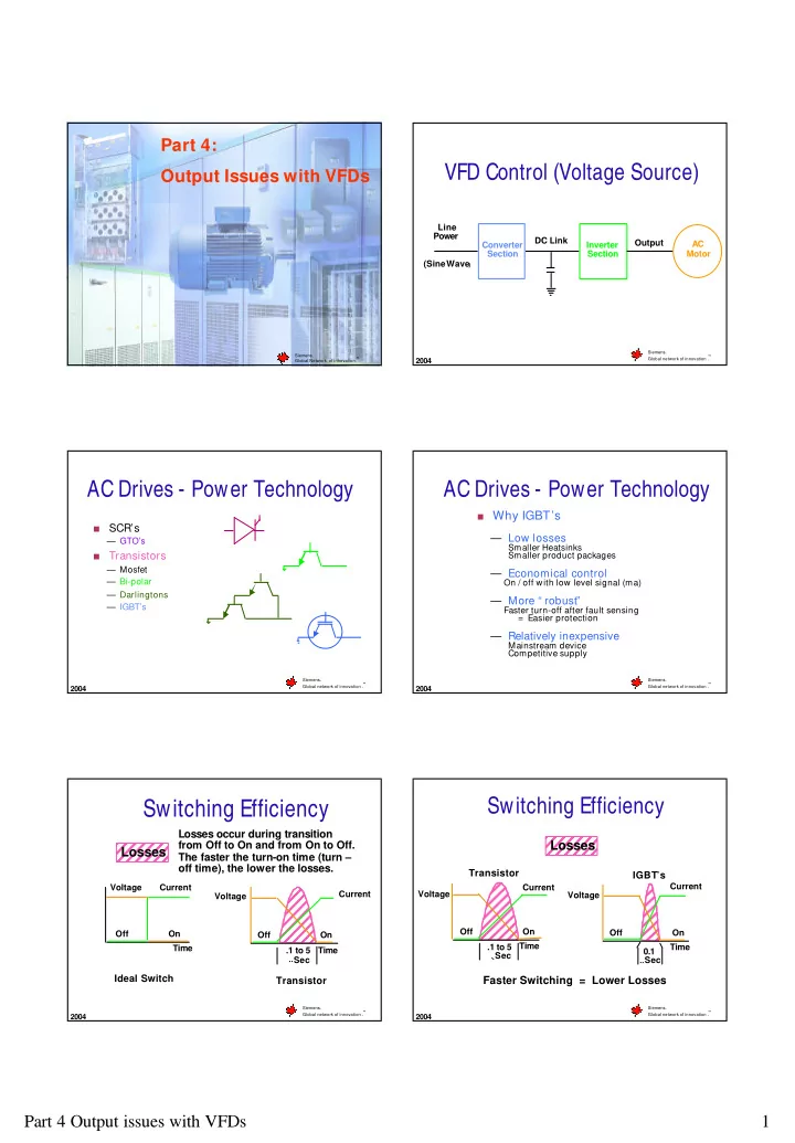
VFD Control (Voltage Source)
Converter Section Inverter Section AC Motor Line Power (Sine Wave
)
DC Link Output
Siemens. Global network of innovation .
2004
AC Drives - Power Technology
a
SCR’s
— GTO’s
a
Transistors
— Mosfet — Bi-polar — Darlingtons — IGBT’s
Siemens. Global network of innovation .
2004
AC Drives - Power Technology
a Why IGBT’s
— Low losses
Smaller Heatsinks Smaller product packages
— Economical control
On / off with low level signal (ma)
— More “ robust”
Faster turn-off after fault sensing = Easier protection
— Relatively inexpensive
Mainstream device Competitive supply
Siemens. Global network of innovation .
2004
Switching Efficiency
Voltage Off On Time
Ideal Switch
Current Voltage Off On Time
Transistor
Current .1 to 5 Sec
Losses
Losses occur during transition from Off to On and from On to Off. The faster the turn-on time (turn –
- ff time), the lower the losses.
Siemens. Global network of innovation .
2004
Switching Efficiency
Voltage Off On Time
Transistor
Current .1 to 5 Sec Voltage Off On Time
IGBT’s
Current 0.1 Sec
Faster Switching = Lower Losses