
SLIDE 1
Su Superconducting g Cable-in in-Co Conduit: ne new techno hnology to ena nabl ble FNSF
Peter McIntyre Accelerator Research Lab Texas A&M University
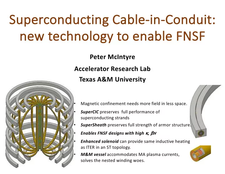
- Magnetic confinement needs more field in less space.
- SuperCIC preserves full performance of
superconducting strands
- SuperSheath preserves full strength of armor structure.
- Enables FNSF designs with high k, bN
- Enhanced solenoid can provide same inductive heating
as ITER in an ST topology.
- M&M vessel accommodates MA plasma currents,
solves the nested winding woes.