study of diameter variation affecting the thermal
play

Study of Diameter Variation Affecting the Thermal Performance of Heat - PDF document

Transactions of the Korean Nuclear Society Virtual Spring Meeting July 9-10, 2020 Study of Diameter Variation Affecting the Thermal Performance of Heat Pipe for Space Nuclear Reactor Applications. Ye Yeong Park, In Cheol Bang * Department of


  1. Transactions of the Korean Nuclear Society Virtual Spring Meeting July 9-10, 2020 Study of Diameter Variation Affecting the Thermal Performance of Heat Pipe for Space Nuclear Reactor Applications. Ye Yeong Park, In Cheol Bang * Department of Nuclear Engineering, Ulsan National Institute of Science and Technology (UNIST) 50 UNIST-gill, Ulju-gun, Ulsan, 44919, Republic of Korea * Corresponding author: icbang@unist.ac.kr 1. Introduction 
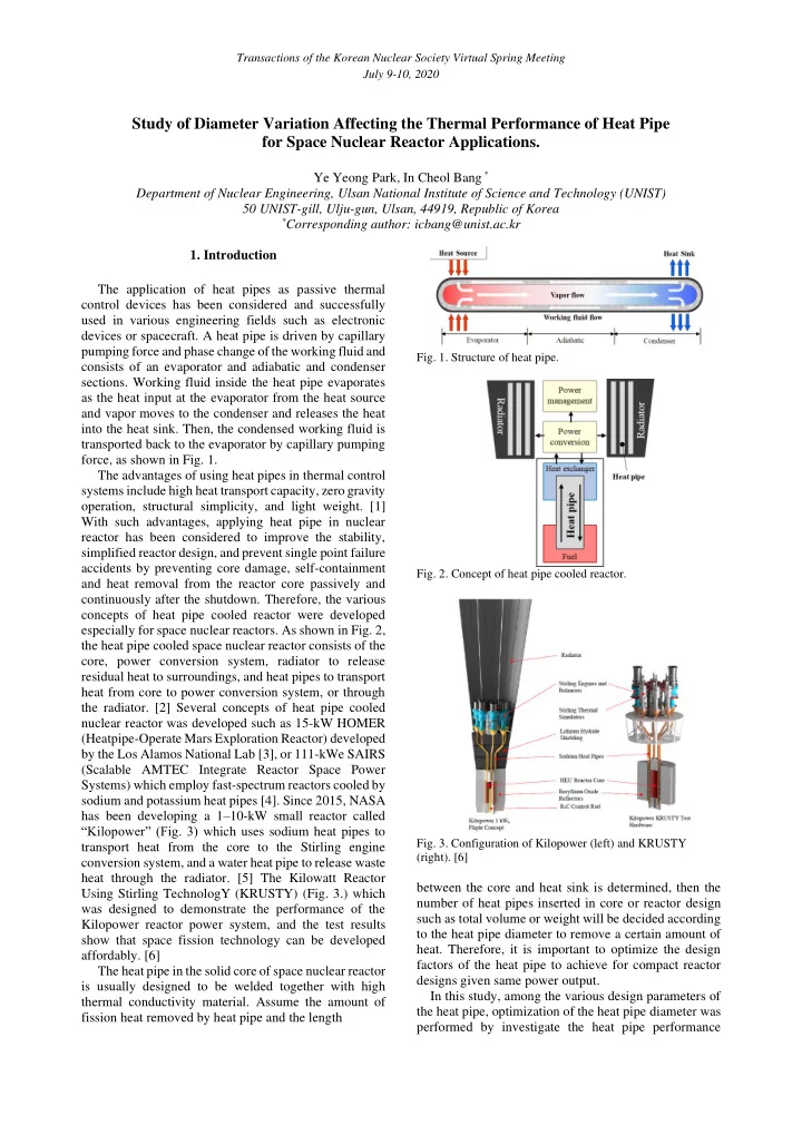
The application of heat pipes as passive thermal control devices has been considered and successfully used in various engineering fields such as electronic devices or spacecraft. A heat pipe is driven by capillary pumping force and phase change of the working fluid and Fig. 1. Structure of heat pipe. consists of an evaporator and adiabatic and condenser sections. Working fluid inside the heat pipe evaporates as the heat input at the evaporator from the heat source and vapor moves to the condenser and releases the heat into the heat sink. Then, the condensed working fluid is transported back to the evaporator by capillary pumping force, as shown in Fig. 1. The advantages of using heat pipes in thermal control systems include high heat transport capacity, zero gravity operation, structural simplicity, and light weight. [1] With such advantages, applying heat pipe in nuclear reactor has been considered to improve the stability, simplified reactor design, and prevent single point failure accidents by preventing core damage, self-containment Fig. 2. Concept of heat pipe cooled reactor. and heat removal from the reactor core passively and continuously after the shutdown. Therefore, the various concepts of heat pipe cooled reactor were developed especially for space nuclear reactors. As shown in Fig. 2, the heat pipe cooled space nuclear reactor consists of the core, power conversion system, radiator to release residual heat to surroundings, and heat pipes to transport heat from core to power conversion system, or through the radiator. [2] Several concepts of heat pipe cooled nuclear reactor was developed such as 15-kW HOMER (Heatpipe-Operate Mars Exploration Reactor) developed by the Los Alamos National Lab [3], or 111-kWe SAIRS (Scalable AMTEC Integrate Reactor Space Power Systems) which employ fast-spectrum reactors cooled by sodium and potassium heat pipes [4]. Since 2015, NASA has been developing a 1 – 10-kW small reactor called “Kilopower” (Fig. 3) which uses sodium heat pipes to Fig. 3. Configuration of Kilopower (left) and KRUSTY transport heat from the core to the Stirling engine (right). [6] conversion system, and a water heat pipe to release waste heat through the radiator. [5] The Kilowatt Reactor between the core and heat sink is determined, then the Using Stirling TechnologY (KRUSTY) (Fig. 3.) which number of heat pipes inserted in core or reactor design was designed to demonstrate the performance of the such as total volume or weight will be decided according Kilopower reactor power system, and the test results to the heat pipe diameter to remove a certain amount of show that space fission technology can be developed heat. Therefore, it is important to optimize the design affordably. [6] factors of the heat pipe to achieve for compact reactor The heat pipe in the solid core of space nuclear reactor designs given same power output. is usually designed to be welded together with high In this study, among the various design parameters of thermal conductivity material. Assume the amount of the heat pipe, optimization of the heat pipe diameter was fission heat removed by heat pipe and the length performed by investigate the heat pipe performance

  2. Transactions of the Korean Nuclear Society Virtual Spring Meeting July 9-10, 2020 according to the length / diameter ratio. Moreover, the experiments will be performed to estimate the thermal performances and deduce the optimal diameter of the heat pipe for space nuclear reactor applications. 2. Heat pipe performance according to diameter 2.1 Operation limits To evaluate the effects of diameter on heat pipe thermal performance, theoretical analysis was performed with existing correlations before the heat pipe experiments. The operation limits determine the maximum heat (a) transfer capacity of the heat pipe which is occurred due to the design limitations such as working fluid properties, wick structure, or operating conditions. If heat load from heat source excess the operation limits, heat pipe performance fails due to dry out in evaporator section. There are several operation limits such as capillary limit, boiling limit, entrainment limit, sonic limit, and viscous limit. The operation limits of the heat pipe according to the heat pipe diameter was investigated with existing correlations [7] for 1 m long heat pipe, 2 layers of 100- mesh screen wick, use water as a working fluid and in horizontal condition. Result in Fig. 4 (a) for 12.7 mm outer diameter show that the viscous limit is the dominant operation limit in lower operating temperature and in higher operating limit region capillary limit (b) determines the maximum heat transfer capacity of the heat pipe. In case of O.D = 19.0 mm and 25.4 mm, capillary limit was shown to be the dominant operation limit in the overall temperature range. 2.2 Pressure drop in heat pipe As the capillary limit was the most dominant operation limit in this case study, and the theoretical analysis with the correlations of pressure drop terms included in capillary limit was performed according to the diameter of the pipe. There are several pressure differences occurred in heat  pipe; gravitational pressure difference ( P ) due to the g (c)  hydrostatic head of liquid, capillary pressure ( ) P Fig. 4. Operation limits according to heat pipe outer diameters cap (a) O.D = 12.7mm, (b) O.D = 19.0 mm, (c) O.D = 25.4 mm. which is the driving force of the heat pipe occurred due to the pressure difference across the curved liquid surface the capillary driving force remain constant when apply in the wick, and the pressure difference caused by same wick structure with same capillary radius, the frictional forces in liquids and vapor flow in a heat pipe. frictional pressure difference of vapor and liquid terms   ( , ) In order for the heat pipe to operate, Eq. (1) P P v l should be analyzed to compare the difference in heat pipe should be satisfied where the maximum capillary driving performance with different diameter. force must overcome the total sum of the pressure drop in right side. For space nuclear reactor, gravitational  2  = pressure can be neglected. P (2) c r    +  +  (1) P P P P cap v l g The pressure drops caused by vapor and liquid is described in Eq. (3) and (4). The pressure difference due The capillary pressure is determined by the capillary to friction forces is affected by the different pipe radius of the heat pipe as described in Eq. (2). Because

Download Presentation
Download Policy: The content available on the website is offered to you 'AS IS' for your personal information and use only. It cannot be commercialized, licensed, or distributed on other websites without prior consent from the author. To download a presentation, simply click this link. If you encounter any difficulties during the download process, it's possible that the publisher has removed the file from their server.

Recommend


More recommend