Solar Air Heater Wizard: Automating CFD Genevive Dutil & - - PowerPoint PPT Presentation

solar air heater wizard automating cfd
SMART_READER_LITE
LIVE PREVIEW

Solar Air Heater Wizard: Automating CFD Genevive Dutil & - - PowerPoint PPT Presentation

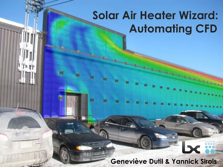
Solar Air Heater Wizard: Automating CFD Genevive Dutil & Yannick Sirois CFD ENGINEERING SIMULATION FEA Lubi TM Collector (perforated glazing) Metal backing (optional) Existing wall Lubi TM panels Spacing clips Vertical extruded bars


slide-1
SLIDE 1

Solar Air Heater Wizard: Automating CFD

Geneviève Dutil & Yannick Sirois

slide-2
SLIDE 2

ENGINEERING SIMULATION

CFD FEA

slide-3
SLIDE 3
slide-4
SLIDE 4

LubiTM Collector (perforated glazing)

Existing wall Metal backing (optional) Spacing clips LubiTM panels Vertical extruded bars

slide-5
SLIDE 5

Goal: Tool to simulate heat transfer in wall before installation to predict and optimize efficiency

slide-6
SLIDE 6

Proposition: Automated CFD analysis from CAD to report through a GUI wizard

slide-7
SLIDE 7

Previous Process

7

Design Building Measurements Design of corrective methods Building Delivery

slide-8
SLIDE 8

New Process

8

Design Simulations Optimization Building Delivery

slide-9
SLIDE 9

Project Stages

  • Simulation Strategy
  • Simulation Model and Validation
  • GUI Programming
  • Optimization case

9

slide-10
SLIDE 10

Simulation Strategy

  • Use of simple geometry elements
  • Porous semi-translucent modeled as

porous baffle

  • No environmental modeling
  • Trimmed cell mesh

10

slide-11
SLIDE 11

Porous Baffle Calibration

  • Detailed

simulation of a section of the perforated plate

11

slide-12
SLIDE 12

Simulation & Validation

  • Four fully instrumented solar collectors

12

slide-13
SLIDE 13

CAD

13

slide-14
SLIDE 14

Temperature and Flow Patterns

14

slide-15
SLIDE 15

Mass Flow Rate & Pressure Drop Across Porous Baffle

15

slide-16
SLIDE 16

Simulation & Validation

  • Simulation outlet temperatures and efficiency

significantly lower than the experimental values

  • Environment plays an important role pre-heating

air before entering the collector

  • Determination of a correction factor to the inlet

temperature influenced by: – Mass flow rate – Inlet temperature – Solar radiation incident to the collector background wall

16

slide-17
SLIDE 17

GUI Programming

17

slide-18
SLIDE 18

GUI Programming

18

slide-19
SLIDE 19

GUI Programming

19

slide-20
SLIDE 20

Optimization Case

20

Single outlet, left side Junction between two sections of different length Wider plenum Side inlet

slide-21
SLIDE 21

Optimization Case

21

slide-22
SLIDE 22

Optimization Case

22

T_in Flow rate Out T out Δη 1) Original design

  • 15.6

°C 13543 CFM 3.4 °C 0 % 2) Outlet centered 6.0 °C. 10.3 % 3) 2+ Blocked top inlet 5.8 °C 9.4 % 4) 2+ Inlets left side 6.4 °C 11.6 % 5) 4 + blocked top inlets 6.3 °C 11.4 % 6) 2 centered outlets + inlets on both sides 6.0 °C 10.4 % 7) 2 centered outlets + no inlets 5.9 °C 9.9 % 8) 6 + blocked top inlets 5.9 °C 9.7 %

slide-23
SLIDE 23

Optimization Case

23

slide-24
SLIDE 24

Benefits of GUI

  • Makes CFD accessible to non-expert

users

  • Optimizes wall configuration before

building

  • Helps in sales: show simulation results

to client

24

slide-25
SLIDE 25

Thank you! Questions?