
SLIDE 1
1 Fall 2005, MIMD
SIMD+ Overview
Early machines Illiac IV (first SIMD) Cray-1 (vector processor, not a SIMD) SIMDs in the 1980s and 1990s Thinking Machines CM-2 (1980s) General characteristics Host computer to interact with user and
execute scalar instructions, control unit to send parallel instructions to PE array
100s or 1000s of simple custom PEs,
each with its own private memory
PEs connected by 2D torus, maybe also
by row/column bus(es) or hypercube
Broadcast / reduction network
2 Fall 2005, MIMD
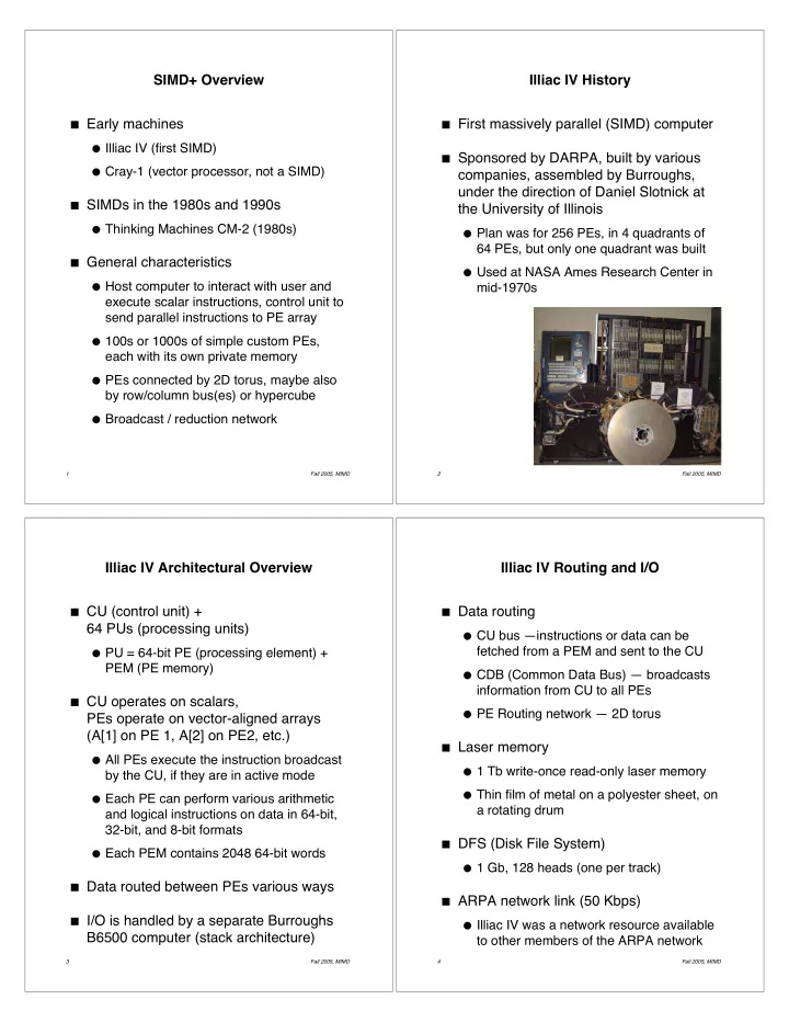
Illiac IV History
First massively parallel (SIMD) computer Sponsored by DARPA, built by various
companies, assembled by Burroughs, under the direction of Daniel Slotnick at the University of Illinois
Plan was for 256 PEs, in 4 quadrants of
64 PEs, but only one quadrant was built
Used at NASA Ames Research Center in
mid-1970s
3 Fall 2005, MIMD
Illiac IV Architectural Overview
CU (control unit) +
64 PUs (processing units)
PU = 64-bit PE (processing element) +
PEM (PE memory)
CU operates on scalars,
PEs operate on vector-aligned arrays (A[1] on PE 1, A[2] on PE2, etc.)
All PEs execute the instruction broadcast
by the CU, if they are in active mode
Each PE can perform various arithmetic
and logical instructions on data in 64-bit, 32-bit, and 8-bit formats
Each PEM contains 2048 64-bit words Data routed between PEs various ways I/O is handled by a separate Burroughs
B6500 computer (stack architecture)
4 Fall 2005, MIMD