
SLIDE 1
CS 251 Fall 2019 Principles of Programming Languages
Ben Wood
λ
CS 240 Spring 2020
Foundations of Computer Systems
Ben Wood https://cs.wellesley.edu/~cs240/s20/
Sequential Logic and State
Output depends on inputs and stored values. (vs. combinational logic: output depends only on inputs) Elements to store values: latches, flip-flops, registers, memory
Latch: CC-BY Rberteig@flickr
Sequential Logic 1
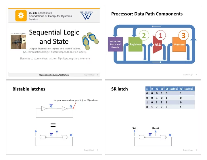
ALU
Processor: Data Path Components
Registers Memory
Instruction Fetch and Decode
1 2 3
Sequential Logic 2
Bistable latches
Q Q
Suppose we somehow get a 1 (or a 0?) on here.
Q Q
=
Sequential Logic 3
SR latch
Q Q R S Set Reset S R Q Q' Q (stable) Q' (stable) 1 1 1 1 1 ? ? 1 1 ? ? 1
Sequential Logic 4