Seismic Attenuation System Synthesis by Reduced Order Models from - - PowerPoint PPT Presentation

seismic attenuation system synthesis by reduced order
SMART_READER_LITE
LIVE PREVIEW

Seismic Attenuation System Synthesis by Reduced Order Models from - - PowerPoint PPT Presentation

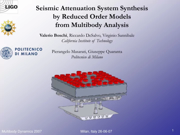
Seismic Attenuation System Synthesis by Reduced Order Models from Multibody Analysis Valerio Boschi , Riccardo DeSalvo, Virginio Sannibale California Institute of Technology Pierangelo Masarati, Giuseppe Quaranta Politecnico di Milano 1


slide-1
SLIDE 1

Multibody Dynamics 2007 Milan, Italy 26-06-07

1

Valerio Boschi, Riccardo DeSalvo, Virginio Sannibale California Institute of Technology Pierangelo Masarati, Giuseppe Quaranta Politecnico di Milano

Seismic Attenuation System Synthesis by Reduced Order Models from Multibody Analysis

slide-2
SLIDE 2

Multibody Dynamics 2007 Milan, Italy 26-06-07

2

Outline

LIGO experiment HAM-SAS attenuation system Reduced Model Extraction Technique (P. Masarati) MBDyn HAM-SAS Model Results and comparison with Experimental data Conclusions

slide-3
SLIDE 3

Multibody Dynamics 2007 Milan, Italy 26-06-07

3

Gravity is not a force, but a property of space-time Einstein’s Equations:

When matter moves, or changes its configuration, its gravitational field changes. This change propagates outward as a ripple in the curvature of space-time: a Gravitational Wave

"Mass tells space-time how to curve, and space-time tells mass how to move.“ John Archibald Wheeler

Gravitational Waves

General Relativity

slide-4
SLIDE 4

Multibody Dynamics 2007 Milan, Italy 26-06-07

4

GW “stretch and compress” every object on their way in perpendicular directions at the frequency of the GW The effect is greatly exaggerated!! If the Vitruvian man were 4.5 light years tall with feet on hearth and head touching the nearest star, he would grow by only a ‘hair width’

Time

Leonardo da Vinci’s Vitruvian man

To directly measure gravitational waves, we need an instrument able to measure tiny relative changes in length, or strain h=ΔL/L

Gravitational Waves

What do they do to matter ?

slide-5
SLIDE 5

Multibody Dynamics 2007 Milan, Italy 26-06-07

5

Pre- Stabilized Laser Mode cleaner Fabry-Perot arm cavity “Reflected” photodiode Power Recycling mirror Input mirror Beam splitter End mirror

Nd:YAG 180 W

GW signal

“Antisymmetric” photodiode

AdLIGO Optical Layout

Signal Recycling mirror Output Mode cleaner

LIGO

4 km 4 km

The experimental challenge: measure differences in length to

  • ne part in 1021 or 10-18 m !!
slide-6
SLIDE 6

Multibody Dynamics 2007 Milan, Italy 26-06-07

6

LIGO

The Observatories

LIGO Livingston Observatory (LLO) L1 : 4 km arms LIGO Hanford Observatory (LHO) H1 : 4 km arms H2 : 2 km arms

slide-7
SLIDE 7

Multibody Dynamics 2007 Milan, Italy 26-06-07

7

LIGO

LIGO Scientific Collaboration (LSC) There are approximately 560 people in the LSC Number of colleges, universities and reasearch institutions: 55 A very complex experiment requires a huge collaboration Caltech Seismic Attenuation System group

slide-8
SLIDE 8

Multibody Dynamics 2007 Milan, Italy 26-06-07

8

LASER

test mass (mirror) photodiode Beam splitter

Quantum Noise "Shot" noise Radiation pressure Seismic Noise Thermal (Brownian) Noise Wavelength & amplitude fluctuations Residual gas scattering

Seismic Noise

LIGO

slide-9
SLIDE 9

Multibody Dynamics 2007 Milan, Italy 26-06-07

9

BSC and HAM vacuum chambers

  • The Corner Station houses the laser,

detector, and all of the optics except the End Test Masses.

  • Each vacuum chamber has an

independently supported, seismically isolated table on which the optics are mounted.

  • The beam tubes are 1.2 m diameter,

low oxygen stainless steel

4 km laser Hanford Observatory 2 km photodiode 2 km laser HAM chamber BSC chamber

  • BSCs are approximately 5.5 m high and hold the beam splitter and the main interferometer mirrors.
  • HAMs are smaller chambers used for the Mode Cleaner and the Recycling cavity mirrors.

4 km photodiode

LIGO

slide-10
SLIDE 10

Multibody Dynamics 2007 Milan, Italy 26-06-07

10

HAM-SAS

HAM-SAS Attenuation Stages

HAM-SAS is a seismic attenuation system designed to provide 70-80 dB of horizontal and vertical attenuation above 10 Hz and to fit in the tight space of the LIGO HAM vacuum chamber.

Rigid Bodies Optical Table (OT) and Payload Top Platform 4 MGAS Springs disposed on a 1.1 x 1 m rectangular configuration. Top + Intermediate Platforms + Springs = Spring Box (SB) Intermediate Platform 4 Inverted Pendula Legs (IPs) disposed on a 1.1 x 0.9 m diamond configuration. Base Platform

slide-11
SLIDE 11

Multibody Dynamics 2007 Milan, Italy 26-06-07

11

HAM-SAS

The Inverted Pendulum (IP) IPs are tunable mechanical oscillators widely used for their good horizontal seismic attenuation performance. Resonant frequencies of tens of millihertz and attenuation factors of 80 dB have been reached experimentally in many systems. A counterweight placed below the IP pivot point allows the center of percussion (COP) of the system to be tuned, and substantially improves the attenuation at high frequency.

TAMA inverted pendulum driven at the shaker resonance IP Legs Actuator

slide-12
SLIDE 12

Multibody Dynamics 2007 Milan, Italy 26-06-07

12

The MGAS

The MGAS filter is a vertical oscillator, developed by the CIT SAS group, which uses a crown of curved blades radially compressed in a horizontal plane for the mechanical vertical compliance. The blades are clamped on one end to a plate, and connected on the other end to a small disk Acting on the position of the clamps one can change the compression of the blade, and tune the MGAS resonant frequency down to 100 mHz

MGAS

HAM-SAS

slide-13
SLIDE 13

Multibody Dynamics 2007 Milan, Italy 26-06-07

13

Key required features for HAM-SAS prototyping:

  • Finite elements for the dynamics of lumped/distributed components
  • Exact kinematics of the joints
  • Possible evaluation of friction, freeplay, …
  • Control sensors and actuators dynamics and control logic
  • Possibility to extract Reduced Order Models (ROM) for control

design All these points may be addressed using the multibody/multidisciplinary approach Currently multibody approach is defined as the merge and blends of various disciplines such as structural dynamics, multi-physics mechanics, control theory and so on, all tackled following classical computational mechanics methodologies.

HAM-SAS Modeling approach

slide-14
SLIDE 14

Multibody Dynamics 2007 Milan, Italy 26-06-07

14

MultiBody Dynamics software developed at POLIMI since early '90s Main application field is rotorcraft dynamics; however, it is currently exploited (@ POLIMI and by 3rd parties) in many projects involving:

Rotorcraft (helicopters & tiltrotors) Aircraft landing gears Robotics and mechatronics Automotive Wind turbines Human body dynamics

MBDyn is free software, meaning that the source code is available for freedom of use, modification and distribution according to the very broad GPL license conditions http://www.aero.polimi.it/~mbdyn/

MBDyn POLIMI multibody software

slide-15
SLIDE 15

Multibody Dynamics 2007 Milan, Italy 26-06-07

15

The following problems may be addressed by MBDyn:

  • Nonlinear mechanics of rigid and flexible bodies
  • Exact constraint kinematics by means of Lagrange multipliers
  • Complex, nonlinear, composite-ready beams
  • Smart materials (e.g. embedded piezo-electrics)
  • Hydraulic components
  • Electric networks
  • Active control logic
  • Aerodynamic steady and unsteady forces

Special features:

  • Direct connection with Matlab/Simulink environment
  • Real-time capabilities under Linux/RTAI extension, for “virtual”

hardware-in-the-loop tests

MBDyn POLIMI multibody software

slide-16
SLIDE 16

Multibody Dynamics 2007 Milan, Italy 26-06-07

16

Implicit Differential-Algebraic Initial-Value Problem: Most integration schemes fall into the scheme Its perturbation yields The “correction” phase results in

Reduced Order Model from Multibody Code

( , , ) y y t = 0

  • F

( ) t = y y

1, 0, k i k i j k j i n j n

a h b

− − = =

= +

∑ ∑

  • y

y y

k k

hb δ δ =

  • y

y

( )

hb δ

  • /y

/y

F + F y = -F

The Problem

slide-17
SLIDE 17

Multibody Dynamics 2007 Milan, Italy 26-06-07

17

Eigenanalysis (non-symmetric, structurally non-definite matrices): right & left (transpose) problems: Requirement: “exact” matrices.

Reduced Order Model from Multibody Code

,

  • /y

F

/y

F

( )

, λ

  • /y

/y

F + F Y =

( )

T T adj

λ

  • /y

/y

F + F Y =

The Problem

slide-18
SLIDE 18

Multibody Dynamics 2007 Milan, Italy 26-06-07

18

Issue: MBDyn computes rather than the required matrices... Proposed solution: extract eigenvalues as where (resembles the inverse of Tustin's transform from continuous to discrete) Possible optimizations for large scale problems discussed in the paper.

Reduced Order Model from Multibody Code

( )

dCoef J = ⋅

  • /y

/y

F + F dCoef 1 dCoef 1 λ λ ⋅ + Λ = ⋅ −

( ) ( )

( )

dCoef dCoef J J Λ⋅ + − = Y

A Solution

slide-19
SLIDE 19

Multibody Dynamics 2007 Milan, Italy 26-06-07

20

Example application: buckling of a simply supported, axially loaded uniform beam

  • Structural dynamics
  • Geometrical nonlinearity
  • Critical buckling load:

2

critical

N EJ L π ⎛ ⎞ = ⎜ ⎟ ⎝ ⎠

Reduced Order Model from Multibody Code

An Application: Simply Supported Beam

slide-20
SLIDE 20

Multibody Dynamics 2007 Milan, Italy 26-06-07

21

First mode shape (N = 0)

Reduced Order Model from Multibody Code

An Application: Simply Supported Beam

slide-21
SLIDE 21

Multibody Dynamics 2007 Milan, Italy 26-06-07

22

First mode frequency as function of N

Reduced Order Model from Multibody Code

An Application: Simply Supported Beam

slide-22
SLIDE 22

Multibody Dynamics 2007 Milan, Italy 26-06-07

23

A state space representation of the linear ROM is obtained by:

  • Mapping the inputs onto the force perturbations
  • Mapping the outputs onto the displacements perturbations
  • Mapping the displacements perturbations onto the selected set of

shapes

  • Shapes are selected from eigenvectors, eventually splitting them in

real and imaginary part in case of complex conjugate eigenvalues

  • State-space matrices result straightforwardly in descriptor form as

~

−Δ = F B u

~

= Δ z C y

~

Δ = y Y x = + =

  • Ex

Ax Bu z Cx

Reduced Order Model from Multibody Code

State-Space Representation

slide-23
SLIDE 23

Multibody Dynamics 2007 Milan, Italy 26-06-07

24

High-frequency modes can be statically residualized: simply supp. beam

Reduced Order Model from Multibody Code

State-Space Representation

slide-24
SLIDE 24

Multibody Dynamics 2007 Milan, Italy 26-06-07

25

Description

The MBDyn model of the HAM-SAS mechanical structure incorporates:

  • 11 Rigid Bodies: 1 massive Base used to excite the system with respect

to the ground in all six DOFs through a force/position actuator, 1 Optical Table, 1 Spring Box, 4 Inverted Pendulum (IP) legs, 4 Little Pendulums;

  • 4 Angular Springs with 3D diagonal stiffness and viscous matrices

representing the flexible joints at the bottom of the IP legs;

  • 4 Linear Springs with 3D diagonal stiffness matrix representing the

MGAS springs;

  • 12 Spherical Joints: 8 connecting the Little Pendulums to the Spring

Box and to the Optical Table, 4 connecting the IP legs to the Base;

  • 8 Displacement Sensors placed on the Spring Box that measure its

position with respect to the Base;

  • 8 Force Actuators placed in the same position of the sensors.

HAM-SAS MBDyn Model

Each spherical joint has been implemented with 3D linear springs, much stiffer (108 N/m) than the elastic elements of the system

slide-25
SLIDE 25

Multibody Dynamics 2007 Milan, Italy 26-06-07

26

HAM-SAS MBDyn Model

2D Sketch Base OT IP Leg LP SB MGAS

Rigid Body COM Effective Spherical Joint

=

Linear Spring K 3D Spherical Spring with viscous damping

= x z y

Kθx Kθy Kθz x

z y

LEGEND

slide-26
SLIDE 26

Multibody Dynamics 2007 Milan, Italy 26-06-07

27

Experimental Results

Measurement setup

Measurements to characterize the performance of HAM-SAS have been done at LASTI (LIGO Advanced System Test Interferometer) facility at MIT.

  • Measurements mechanical

system were done under vacuum to eliminate acoustic noise, air flow perturbations, and to reduce thermal drifts

  • Co-located sensing and actuation

SISO and MIMO control strategy were successfully tested for DC control and damping low frequency resonances.

  • A Stabilizing device (not visible)

retrofitted to solve a pitch and roll instability caused by the high center of mass of the optical table’s payload has been made using helical springs and wires

Payload (Optics) Optical Table Spring Box S/A

slide-27
SLIDE 27

Multibody Dynamics 2007 Milan, Italy 26-06-07

28

Measurement setup

Experimental Results

  • Six unidirectional geophones were placed on the optical table and suitably
  • riented to detect the residual excitation of all the six DOF.

Similarly, three tri-axial force-feedback seismometers measured the six-DOF excitation of the ground. The ambient anthropogenic noise was used as excitation for the measurements.

Geophones

slide-28
SLIDE 28

Multibody Dynamics 2007 Milan, Italy 26-06-07

29

Experimental Results

Horizontal Transmissibilities

65 mHz IP frequency 60 Hz Effective spherical joints 265 mHz Horizontal GAS frequency 22 Hz Little pendulums 125 mHz DOF Crosscoupling 15-30 Hz Internal resonances due to the stabilizing device

slide-29
SLIDE 29

Multibody Dynamics 2007 Milan, Italy 26-06-07

30

Experimental Results

Vertical Transmissibilities

100 mHz MGAS Vertical frequency

Angular degrees of freedom measurements are not shown due to the their low coherences

slide-30
SLIDE 30

Multibody Dynamics 2007 Milan, Italy 26-06-07

31

Linearization Results

65 mHz IP frequency 60 Hz Effective spherical joints 265 mHz Horizontal GAS frequency 22 Hz Little pendulums 100 mHz MGAS Vertical frequency

slide-31
SLIDE 31

Multibody Dynamics 2007 Milan, Italy 26-06-07

32

Perspectives and Conclusions

The work presented a technique to extract reduced order models, using normal modes, from the problem matrix generated by MBDyn. The technique has been applied to LIGO HAM-SAS mechanical system and validated with experimental data. Future developments: A non-linear model of MGAS will be developed The reduced models will be used for control design We will probably test MBDyn real-time extension capabilities MBDyn can be useful in many other mechanical subsystems of LIGO and will be probably integrated in e2e, LIGO dedicated simulation package

slide-32
SLIDE 32

Multibody Dynamics 2007 Milan, Italy 26-06-07

33

Acknowledgements

The LIGO Observatories were constructed by the California Institute

  • f Technology and Massachusetts Institute of Technology with funding

from the National Science Foundation under cooperative agreement PHY 9210038.

Thank you for your attention