
SLIDE 1
S.E.V Solar Extended Vehicle EEL 4914 Senior Design II Group #4 - - PowerPoint PPT Presentation
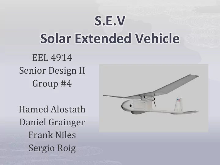
S.E.V Solar Extended Vehicle EEL 4914 Senior Design II Group #4 Hamed Alostath Daniel Grainger Frank Niles Sergio Roig Motivation The majority of electric motor RC planes tend to have a low flight time Solar panels are not
Electronic Speed Controller Receiver Remote Controller Motor Servo2 Servo1
Solar Extended Vehicle µController GPS 3-axis Gyroscope 3-axis Accelerometer Solar panels Charging Circuit Battery
µController
ATmega328 LY530ALH Z-axis LPR530AL X/Y axis ADXL335 X/Y/Z axes MT3329 GPS
ATmega328 LY530ALH LPR530AL ADXL335 MT3329 Sample $9.95 $7.95 $9.95 $63.51 1.8 – 5.5 V 3 V 3 V 3V 4.5 – 6.5 V 8-channel 10-bit ADC Analog Output Analog Output Analog Output Rx/Tx
ATmega328 ATtiny45 Xbee-Pro 900MHz 2.4G 6-channel Receiver Throttle/Rudder/Elevator Ground Station Laptop Xbee-Pro 900MHz 2.4G DX5e 5-channel Transmitter
ATtiny45 Xbee-Pro (RF) RC Rx (RF) Sample $95.37 $9.00 1.8 – 5.5 V 3 – 3.6 V 4.5 – 6.5 V
2.4 GHz UART UART
ATmega328 GPS MT3329 X/Y LPR530AL ADXL335 X/Y/Z Motor Servos Battery Xbee pro RC Tx @ Ground Station ATmega328 Z LY530ALH Solar Arrays RC Rx @ 2.4 GHz ADC SDA/SCL SDA/SCL ATtiny45 Xbee pro @ 900 MHz UART Tx/Rx ESC Tx/Rx Charging Circuit Servos SDA/SCL
PWM
Autopilot Circuit Board Single and dual axis Gyroscopes Accelerometer Center of Gravity Connectors: Charging- Circuit Circuit-Board, GPS, Xbee-Pro, and Servos
PowerFilm RC7.2-75
Panel SolMaxx Flex 7.2V 100mA SolMaxx Flex 7.2V 200mA PowerFilm RC7.2-75 Dimensions: 10.6” x 3.9” 10.6” x 6.9” 10.6” x 3.5” Weight: 1.1 oz 1.9 oz 0.2 oz Total Weight: 8.8 oz 7.6 oz 1.6 oz Thickness: NA NA 0.2 mm Voltage: 7.2V 7.2V 7.2V Total Output: 291 mA @ 19.8V 291mA 19.8V 291mA 19.8V Price: $20.95 ea. $37.75 ea. $27.45 ea.
19.8V @ 291 mA
Type: LiPo Capacity: 3200mAh Voltage: 11.1V Connector Wire Gauge: 12 AWG Weight: 9.9 oz (251g) Configuration: 3S Length: 5.20 in (132mm) Width: 1.70 in (43.2mm) Height: 0.90 in (22.9mm) Maximum Continuous Discharge : 15C Maximum Continuous Current : 48A
MPPT or Maximum Power Point Tracking is an algorithm that included in charge controllers used for extracting maximum available power from PV module under certain conditions. The voltage at which PV module can produce maximum power is called ‘maximum power point’ (or peak power voltage). Maximum power varies with:
Li-Ion/Polymer, LiFePO4, SLA, NiMH/NiCd Chemistries
monitor the minimum amount of voltage coming into the MPPT. The input supply voltage regulation is controlled via the voltage divider resistor RIN1 and RIN2. An operating supply voltage can be programmed by monitoring the supply through the resistor divider
minimum voltage. In order to achieve the 11.1V needed:
RIN1/RIN2 = (VIN(MIN)/2.7) - 1 RIN1/RIN2= 12.185
RFB1= (VBAT(FLT) * 2.5 * 105)/3.3 RFB1= 943.18 KΩ RFB2 = (R1*(2.5*105))/(R1*(2.5*105)) RFB2= 340.16 KΩ
RSENSE = 0.1/ICHG(MAX) RSENSE= 0.2161 Ω
loop.
three Functions.
radio controller is sending a signal, it will calculate the altitude and bearing error and last will update current flight mode.
5 different cases that will be executed one at a time. These cases range from navigation to
checks to see if the control switch has been changed.
servo_out[CH_THROTTLE] = temp_thro; if(current_loc.alt < 3000){ temp_thro = THROTTLE_MAX; servo_out[CH_THROTTLE] = THROTTLE_MAX; nav_roll = 0 ; nav_pitch = 1500; } if(current_loc.alt > 6000){ temp_thro = THROTTLE_MIN; servo_out[CH_THROTTLE] = THROTTLE_MIN; nav_roll = HEAD_MAX / 3; nav_pitch = 500; }
tested the software.
environment, we chose to do this to avoid destroying our airframes
to simulate the software code.
development boards purchased from SparkFun
Description Quantity Price Each Total Price
Plane 1 $89.95 $119.80 Motor 1 $54.99 $58.56 Prototype plane incl. servo & ESC 2 Incl $300.00 Electronic Speed Controller 1 Incl Incl Microcontroller ATmega 328 & ATtiny45 1 Sample Free Triple-Axis Accelerometer- ADXL335 1 $5.00 $5.00 Barometric Pressure Sensor – BMP085 1 Sample Free Gyroscope LY530ALH & LPR530AL 2 Sample Free GPS Mediatech MT3329 1 $63.51 $63.51 Transmitter/ Receiver 1 $32.78 $32.78 Zigbee Pro 2 $47.69 $95.37 Solar Panel PowerFilm RC7.2-75 8 $31.34 $250.69 Lithium-Ion Polymer Battery Pack 2 $53.24 $106.48 LT3652 Charging Circuit 2 $27.98 $48.88 Sub-Total $1,023.00
Group IV Power Software Design Hardware Design Air Frame Mechanics Hamed Alostath √ √ Daniel Grainger √ √ Frank Niles √ √ Sergio Roig √ √