
SLIDE 1
35mm RAO LAO 45mm
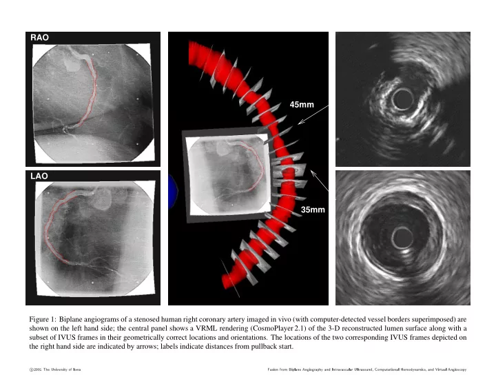
Figure 1: Biplane angiograms of a stenosed human right coronary artery imaged in vivo (with computer-detected vessel borders superimposed) are shown on the left hand side; the central panel shows a VRML rendering (CosmoPlayer 2.1) of the 3-D reconstructed lumen surface along with a subset of IVUS frames in their geometrically correct locations and orientations. The locations of the two corresponding IVUS frames depicted on the right hand side are indicated by arrows; labels indicate distances from pullback start.
c 2001 The Universit y- f