
October 2013
RADIX 2/10 – SYSTEM LEIBNIZ
10 Bit Binary/Decimal Desktop Slide Rule By C Tombeur
OVERVIEW
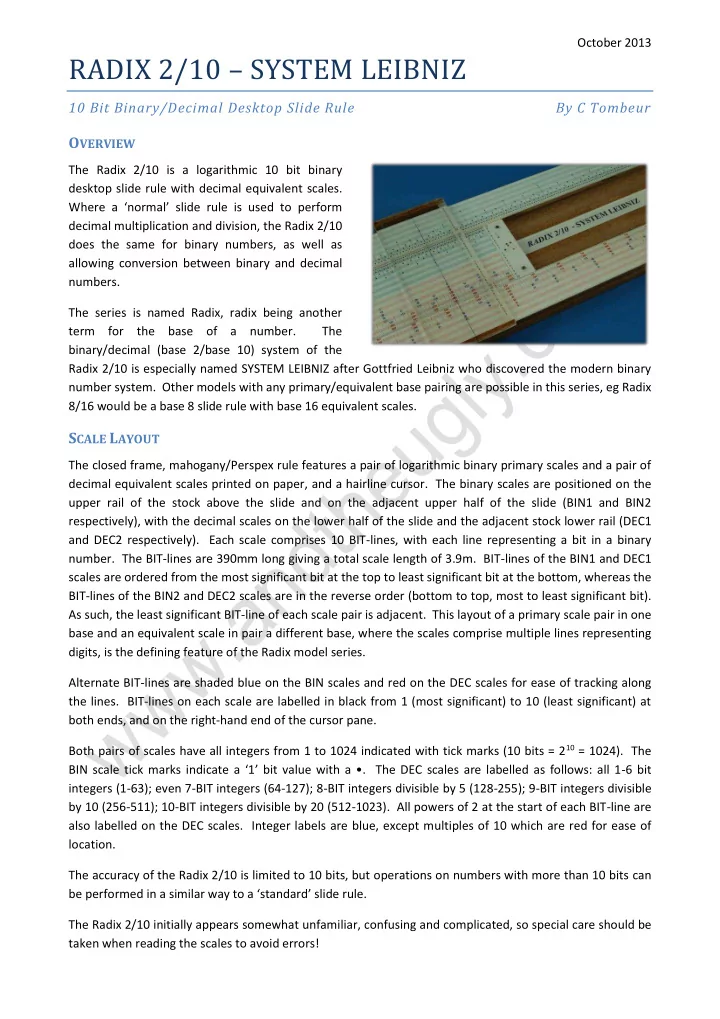
The Radix 2/10 is a logarithmic 10 bit binary desktop slide rule with decimal equivalent scales. Where a ‘normal’ slide rule is used to perform decimal multiplication and division, the Radix 2/10 does the same for binary numbers, as well as allowing conversion between binary and decimal numbers. The series is named Radix, radix being another term for the base of a number. The binary/decimal (base 2/base 10) system of the Radix 2/10 is especially named SYSTEM LEIBNIZ after Gottfried Leibniz who discovered the modern binary number system. Other models with any primary/equivalent base pairing are possible in this series, eg Radix 8/16 would be a base 8 slide rule with base 16 equivalent scales.
SCALE LAYOUT
The closed frame, mahogany/Perspex rule features a pair of logarithmic binary primary scales and a pair of decimal equivalent scales printed on paper, and a hairline cursor. The binary scales are positioned on the upper rail of the stock above the slide and on the adjacent upper half of the slide (BIN1 and BIN2 respectively), with the decimal scales on the lower half of the slide and the adjacent stock lower rail (DEC1 and DEC2 respectively). Each scale comprises 10 BIT-lines, with each line representing a bit in a binary
- number. The BIT-lines are 390mm long giving a total scale length of 3.9m. BIT-lines of the BIN1 and DEC1
scales are ordered from the most significant bit at the top to least significant bit at the bottom, whereas the BIT-lines of the BIN2 and DEC2 scales are in the reverse order (bottom to top, most to least significant bit). As such, the least significant BIT-line of each scale pair is adjacent. This layout of a primary scale pair in one base and an equivalent scale in pair a different base, where the scales comprise multiple lines representing digits, is the defining feature of the Radix model series. Alternate BIT-lines are shaded blue on the BIN scales and red on the DEC scales for ease of tracking along the lines. BIT-lines on each scale are labelled in black from 1 (most significant) to 10 (least significant) at both ends, and on the right-hand end of the cursor pane. Both pairs of scales have all integers from 1 to 1024 indicated with tick marks (10 bits = 210 = 1024). The BIN scale tick marks indicate a ‘1’ bit value with a •. The DEC scales are labelled as follows: all 1-6 bit integers (1-63); even 7-BIT integers (64-127); 8-BIT integers divisible by 5 (128-255); 9-BIT integers divisible by 10 (256-511); 10-BIT integers divisible by 20 (512-1023). All powers of 2 at the start of each BIT-line are also labelled on the DEC scales. Integer labels are blue, except multiples of 10 which are red for ease of location. The accuracy of the Radix 2/10 is limited to 10 bits, but operations on numbers with more than 10 bits can be performed in a similar way to a ‘standard’ slide rule. The Radix 2/10 initially appears somewhat unfamiliar, confusing and complicated, so special care should be taken when reading the scales to avoid errors!