RADAR ABSORBING STRUCTURE WITH PERIODIC PATTERN SURFACES FOR WIND - - PDF document

radar absorbing structure with periodic pattern surfaces
SMART_READER_LITE
LIVE PREVIEW

RADAR ABSORBING STRUCTURE WITH PERIODIC PATTERN SURFACES FOR WIND - - PDF document

18 TH INTERNATIONAL CONFERENCE ON COMPOSITE MATERIALS RADAR ABSORBING STRUCTURE WITH PERIODIC PATTERN SURFACES FOR WIND TURBINE BLADES H. K. Jang 1 , W. H. Choi 1 , J. H. Shin 1 , T. H. Song 1 , J. K. Kim 1 , C. G. Kim 1 *, J. B. Kim 2 , D. W. Lim


slide-1
SLIDE 1

18TH INTERNATIONAL CONFERENCE ON COMPOSITE MATERIALS

1 Introduction The wind and solar power is considered a promising alternative energy because of the limitless resources, pollution-free, and environmentally-friendly. Among them, the wind energy is a fast growing market and increasing at the rate of 30 % annually. However, large radar cross section (RCS) of wind tower and high tip speed of wind blades can affect surrounding infrastructures using commercial and military radar

  • system. The rotor blades cause a Doppler problem

and the wind installation, such as blade, tower, and nacelle, is enough to generate false plots by clutter and shadowing. Thus a number of proposed wind farm projects have been stopped and cancelled in the world [1-2]. These problems can be solved by development of stealth wind turbine blades which incorporate a radar absorbing structure (RAS) into the structure of wind

  • blades. The RAS will allow wind blades to absorb

incident radar signals without compromising their structural strength, while reducing or eliminating the signals received by radar system [3-5]. The purpose

  • f this paper is to present the radar absorbing

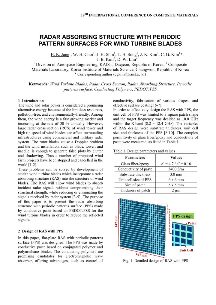
structure with periodic patterns surface (PPS) made by conductive paste based on PEDOT:PSS for the wind turbine blades in order to reduce the reflected signals. 2 Design of RAS with PPS In this paper, flat-plate RAS with periodic patterns surface (PPS) was designed. The PPS was made by conductive paste based on conjugated polymer and polyurethane binder. The conducting polymers are promising candidates for electromagnetic wave absorber, offering advantages, such as control of conductivity, fabrication of various shapes, and effective surface coating [6-7]. In order to effectively design the RAS with PPS, the unit cell of PPS was limited to a square patch shape and the target frequency was decided as 10.0 GHz within the X-band (8.2 ~ 12.4 GHz). The variables

  • f RAS design were substrate thickness, unit cell

size and thickness of the PPS [8-10]. The complex permittivity of glass fiber/epoxy and conductivity of paste were measured, as listed in Table 1. Table 1. Design parameters and values Parameters Values Glass fiber/epoxy ε΄ = 4.7 / ε˝ = 0.16 Conductivity of paste 3400 S/m Substrate thickness 3.0 mm Unit cell size of PPS 6 x 6 mm Size of patch 5 x 5 mm Thickness of patch 2 µm

147 mm

PPS design

Unit Cell Patch

  • Fig. 1. Detailed design of RAS with PPS

RADAR ABSORBING STRUCTURE WITH PERIODIC PATTERN SURFACES FOR WIND TURBINE BLADES

  • H. K. Jang1, W. H. Choi1, J. H. Shin1, T. H. Song1, J. K. Kim1, C. G. Kim1*,
  • J. B. Kim2, D. W. Lim2

1 Division of Aerospace Engineering, KAIST, Daejeon, Republic of Korea, 2 Composite

Materials Laboratory, Korea Institute of Materials Science, Changwon, Republic of Korea

* Corresponding author (cgkim@kaist.ac.kr)

Keywords: Wind Turbine Blades, Radar Cross Section, Radar Absorbing Structure, Periodic patterns surface, Conducting Polymers, PEDOT:PSS

slide-2
SLIDE 2

Figure 1 shows the detailed design of flat-plate RAS with PPS using conductive paste. The geometry of designed RAS was 147 x 147 x 3.0 mm, which excludes conductor thickness of 0.1 mm. The unit cell size of PPS was 6 x 6 mm and the patch size was 5 x 5 x 0.002 mm.

5 6 7 8 9 10 11 12 13 14 15

  • 50
  • 40
  • 30
  • 20
  • 10

10 Reflection Loss (dB) Frequency (GHz) RAS with PPS

  • Fig. 2. Reflection loss of RAS with PPS

In order to evaluate the radar absorbing performance

  • f RAS, reflection loss (RL) and radar across section

(RCS) of designed RAS with PPS were simulated by commercial electromagnetic field analysis program, CST-MWS. According to the simulation results of reflection loss, the designed RAS had a minimum reflection loss of - 39.2 dB at 10.0 GHz, meaning that over 99 % of incident energy was absorbed. The

  • 10 dB bandwidth, 90 % radar absorption was

almost 4.8 GHz (7.9 ~ 12.7 GHz), covering the entire X-band, as shown in Fig. 2.

  • 90
  • 60
  • 30

30 60 90

  • 30
  • 25
  • 20
  • 15
  • 10
  • 5

5 10 15 Radar Cross Section (dBsm) Incident Angel (°) Metal plate RAS with PPS

  • Fig. 3. Comparison of RCS at 10.0 GHz

Figure 3 and 4 show the comparison of radar cross section between metal plate and RAS with PPS, which have a same geometric shape. According to the simulation results of monostatic radar, the RCS

  • f designed RAS was decreased as compared with

non-radar absorber at the all direction of 10.0 GHz. In the case of normal incident angle (0º), the RCS declined by nearly 99 %, from 9.1 to - 9.9 dBsm, at the target frequency of 10.0 GHz.

8.4 8.8 9.2 9.6 10.0 10.4 10.8 11.2 11.6 12.0 12.4

  • 20
  • 15
  • 10
  • 5

5 10 15 20 Radar Cross Section (dBsm) Frequency (GHz) Metal plate RAS with PPS

  • Fig. 4. Comparison of RCS within X-band

Figure 4 shows the RCS of metal plate and RAS with PPS in the normal incident angle within X-band. According to the simulation results, the RCS was decreased more than 80 % on the whole frequency

  • band. In case of 10.0 GHz,

3 Fabrication of RAS with PPS Manufacturing process of RAS with PPS consists of two phases, a metal mask printing step, and a resin transfer step. The metal mask printing method is to make the periodic patterns surface using conductive paste and resin transfer method is to fabricate the load-bearing structure. The designed RAS with PPS was fabricated through the two steps. In this paper, the periodic patterns surface was made by screen printing method using a patterned metal mask and conductive paste. The patterned metal mask was made of SUS 304 of 100 µm thickness. The conducting polymer paste for resistive sheet of radar absorber was synthesized using water-soluble polyurethane binder, NPC 3600 (Nanux Co., Ltd.), and poly(3,4- ethylenedioxythiophene):poly(styrene- sulfonate), Clevios PH 500 (Heraeus Co., Ltd.).

slide-3
SLIDE 3

Figure 5. shows the process of metal mask printing using paste and completed periodic patterns on the glass fiber/epoxy composite sheet, GEP 110 (plain- weave E-glass fiber, SK Chemical Co., Ltd).

Metal mask PPS

  • Fig. 5. Metal mask printing method

The structure as load-bearing and spacer for RAS was fabricated by resin transfer method. Dielectric layer was made of bidiagonal-glass-fabric (NCF ± 45º E-glass fiber, Saertex Co., Ltd.) and conductor layer was made of WSN 3K (plain-weave carbon fiber, SK Chemical Co., Ltd.).

PPS Carbon fiber Glass fiber Infusion resin (In) Vacuum bag Infusion resin (Out)

  • Fig. 6. Resin transfer method

Binding matrix was a mixture of epoxy resin RIM 135 and hardener RIMH 134 (Hexion Co., Ltd.), the mixing ratio of infusion resin was 100 : 30. The PPS, NCF ± 45º E-glass fiber, and WSN 3K were stacked up and then the binding matrix was infused into the vacuum bag through the in-out line, as shown in Fig.

  • 6. In this case, the infusion resin was cured for 2

days at the room temperature. Figure 7. shows the configuration of RAS with PPS, which was made by RTM process

Periodic Patterns Surface Glass fiber/epoxy Carbon fiber/epoxy

  • Fig. 7. Configuration of RAS with PPS

4 Discussion and conclusion In this paper, radar absorbing structure with periodic patterns surface was designed and fabricated in order to reduce the reflected signals from wind blades. The designed RAS had a minimum reflection loss of

  • 39.2 dB at 10.0 GHz and - 10 dB bandwidth was

almost 4.8 GHz (7.9 ~ 12.7 GHz). The RCS declined by nearly 99 % at the target frequency and was decreased more than 80 % on the whole X-band. The designed periodic patterns surface was made by metal mask printing method using conductive paste. The structure as load-bearing and spacer for RAS was fabricated by resin transfer method using fiber reinforced composites and infusion resin. From the study on a low reflective structure against radar signals, RAS with PPS was suggested and

  • verified. Also, the fabrication process of RAS was

developed considering the manufacture of real scale wind blades and materials for wind blades were used to make the RAS. Finally, the feasibility of stealth

slide-4
SLIDE 4

rotor blades to minimize the signal interference with surrounding infrastructures was presented. Acknowledgement This work was supported by New & Renewable Energy R&D program (2008-N-WD08-P-02) under the Korea Ministry of Knowledge Economy (MKE) and Defense Acquisition Program Administration and Agency for Defense Development under the contract UD100048JD. References

[1] M. M. Butlerand, D. A. Johnson “Feasibility of mitigating the effects of wind farms on primary radar”. Project report, 2003. [2] G. J. Poupart “Wind farms impact on radar aviation interests – final report”. Project report, 2003 [3] A. Tennant, B. Chambers “Signature management of radar returns from wind turbine generators”. Smart Materials and Structures, Vol. 15, No. 2, pp 468-472, 2006. [4] E. F. Knott, J. F. Shaeffer, M. T. Tuley “Radar cross section”. 2nd edition, SciTech Publishing, 2004. [5] K. J. Vinoy, R. M. Jha “Radar absorbing materials: from theory to design and characterization”. 1st edition, Kluwer Academic Publishers, 1996. [6] M. H. Harun, E. Saion, A. Kassim, N. Yahya, E. Mahmud “Conjugated conducting polymers: a brief

  • verview”. Journal for the Advancement of Science

and Arts, Vol. 2, No. 63, pp. 63-68, 2007. [7] P. T. C. Wong, B. Chamber, A. P. Anderson, P. V. Wright “Large area conducting polymer composites and their use in microwave absorbing material”. Electronic Letters, Vol. 28, pp1651-1653, 1992. [8] B. A. Munk “Frequency selective surfaces: theory and design”. 1st edition, Wiley-Interscience, 2000. [9] H. K. Jang, W. J. Lee, C. G. Kim “Design and fabrication of a microstrip patch antenna with a low radar cross section in the X-band”. Smart Materials and Structures, Vol. 20, No. 1, pp. 1-8, 2011. [10] H. K. Jang, J. H. Shin, C. G. Kim, S. H. Shin, J. B. Kim “Semi-cylindrical Radar Absorbing Structures using Fiber-reinforced Composites and Conducting Polymers in the X-band”. Advanced Composite Materials, Vol. 20, No. 2, pp. 215-229, 2011.