
SLIDE 1
Thomas Jefferson National Accelerator Facility
Operated by the Southeastern Universities Research Association for the U.S. Department of Energy
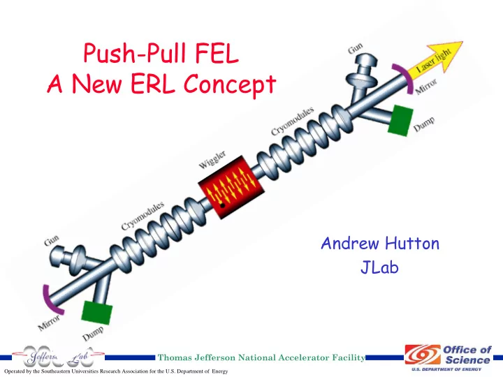
Push-Pull FEL A New ERL Concept Andrew Hutton JLab Thomas - - PowerPoint PPT Presentation
Push-Pull FEL A New ERL Concept Andrew Hutton JLab Thomas Jefferson National Accelerator Facility Operated by the Southeastern Universities Research Association for the U.S. Department of Energy Drivers for a New Concept The ILC will use
Thomas Jefferson National Accelerator Facility
Operated by the Southeastern Universities Research Association for the U.S. Department of Energy
Operated by the Southeastern Universities Research Association for the U.S. Department of Energy
Thomas Jefferson National Accelerator Facility
Page 2
Operated by the Southeastern Universities Research Association for the U.S. Department of Energy
Thomas Jefferson National Accelerator Facility
Page 3
Operated by the Southeastern Universities Research Association for the U.S. Department of Energy
Thomas Jefferson National Accelerator Facility
Page 4
Operated by the Southeastern Universities Research Association for the U.S. Department of Energy
Thomas Jefferson National Accelerator Facility
Page 5
CRYOCAVITY CRYOCAVITY
Operated by the Southeastern Universities Research Association for the U.S. Department of Energy
Thomas Jefferson National Accelerator Facility
Page 6
Operated by the Southeastern Universities Research Association for the U.S. Department of Energy
Thomas Jefferson National Accelerator Facility
Page 7
Operated by the Southeastern Universities Research Association for the U.S. Department of Energy
Thomas Jefferson National Accelerator Facility
Page 8
Operated by the Southeastern Universities Research Association for the U.S. Department of Energy
Thomas Jefferson National Accelerator Facility
Page 9
Parameter 10 kW JLab FEL Push-Pull FEL Design Design Maximum Beam Energy 80 – 210 MeV 200 MeV Injector Beam Energy 10 MeV 10 MeV Beam Current 10 mA 2 x 0.5 mA Beam Power 800 – 2100 kW 2 x 100 kW Non-Recovered Beam Power 100 kW 2 x 5 kW RF Frequency 1500 MHz 1300 MHz FEL Repetition Rate 3.9 – 125 MHz RF Frequency/(4 – 384) 5.078 MHz RF Frequency/256 Optical Cavity Length 32 meter 29.539 meter Bunch Charge 135 pC @ 75 MHz 100 pC Energy Spread after Wiggler 10% of 210 MeV 2.5% of 200 MeV Energy Spread at Dump ~2% of 10 MeV 50% of 10 MeV FEL Output Power 10 kW in the Infrared 1 kW in the UV > 1 kW in the UV with bunch compression
Operated by the Southeastern Universities Research Association for the U.S. Department of Energy
Thomas Jefferson National Accelerator Facility
Page 10
Operated by the Southeastern Universities Research Association for the U.S. Department of Energy
Thomas Jefferson National Accelerator Facility
Page 11
100 200 300 400 500 0.0 0.1 0.2 0.3 0.4 0.5
0% 10% 20% 30% 40% 50% 60% 70% 80% 0.0 0.1 0.2 0.3 0.4 0.5
Operated by the Southeastern Universities Research Association for the U.S. Department of Energy
Thomas Jefferson National Accelerator Facility
Page 12
Operated by the Southeastern Universities Research Association for the U.S. Department of Energy
Thomas Jefferson National Accelerator Facility
Page 13
200 400 600 800 1000 1200 1400 1600 0.0 0.1 0.2 0.3 0.4 0.5
0% 50% 100% 150% 200% 250% 300% 350% 400% 450% 0.0 0.1 0.2 0.3 0.4 0.5
Operated by the Southeastern Universities Research Association for the U.S. Department of Energy
Thomas Jefferson National Accelerator Facility
Page 14
Operated by the Southeastern Universities Research Association for the U.S. Department of Energy
Thomas Jefferson National Accelerator Facility
Page 15
Operated by the Southeastern Universities Research Association for the U.S. Department of Energy
Thomas Jefferson National Accelerator Facility
Page 16
Operated by the Southeastern Universities Research Association for the U.S. Department of Energy
Thomas Jefferson National Accelerator Facility
Page 17
Operated by the Southeastern Universities Research Association for the U.S. Department of Energy
Thomas Jefferson National Accelerator Facility
Page 18
Operated by the Southeastern Universities Research Association for the U.S. Department of Energy
Thomas Jefferson National Accelerator Facility
Page 19
Parameter 10 kW JLab FEL Push-Pull FEL Design Design Maximum Beam Energy 80 – 210 MeV 200 MeV Injector Beam Energy 10 MeV 10 MeV Beam Current 10 mA 2 x 0.5 mA Beam Power 800 – 2100 kW 2 x 100 kW Non-Recovered Beam Power 100 kW 2 x 5 kW RF Frequency 1500 MHz 1300 MHz FEL Repetition Rate 3.9 – 125 MHz RF Frequency/(4 – 384) 5.078 MHz RF Frequency/256 Optical Cavity Length 32 meter 29.539 meter Bunch Charge 135 pC @ 75 MHz 100 pC Energy Spread after Wiggler 10% of 210 MeV 2.5% of 200 MeV Energy Spread at Dump ~2% of 10 MeV 50% of 10 MeV FEL Output Power 10 kW in the Infrared 1 kW in the UV > 1 kW in the UV with bunch compression