Protocol Stack Networking Email Generally speaking, sending an - - PDF document

protocol stack networking
SMART_READER_LITE
LIVE PREVIEW

Protocol Stack Networking Email Generally speaking, sending an - - PDF document

Protocol Stack Networking Email Generally speaking, sending an email message is equivalent to copying a file from sender to receiver. Packetization Representation It is impossible to send arbitrary long messages. Correspondents may


slide-1
SLIDE 1

1

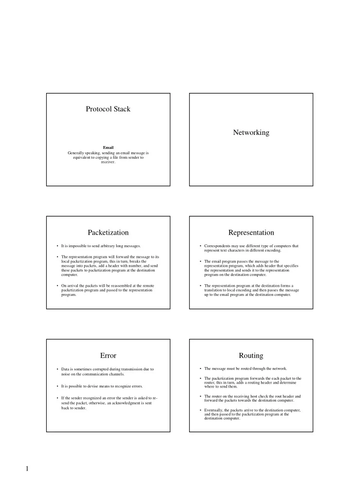
Networking Protocol Stack

Email Generally speaking, sending an email message is equivalent to copying a file from sender to receiver.

Representation

  • Correspondents may use different type of computers that

represent text characters in different encoding.

  • The email program passes the message to the

representation program, which adds header that specifies the representation and sends it to the representation program on the destination computer.

  • The representation program at the destination forms a

translation to local encoding and then passes the message up to the email program at the destination computer.

Packetization

  • It is impossible to send arbitrary long messages.
  • The representation program will forward the message to its

local packetization program, this in turn, breaks the message into packets, add a header with number, and send these packets to packetization program at the destination computer.

  • On arrival the packets will be reassembled at the remote

packetization program and passed to the representation program.

Routing

  • The message must be routed through the network.
  • The packetization program forwards the each packet to the

router, this in turn, adds a routing header and determine where to send them.

  • The router on the receiving host check the rout header and

forward the packets towards the destination computer.

  • Eventually, the packets arrive to the destination computer,

and then passed to the packetization program at the destination computer.

Error

  • Data is sometimes corrupted during transmission due to

noise on the communication channels.

  • It is possible to devise means to recognize errors.
  • If the sender recognized an error the sender is asked to re-

send the packet, otherwise, an acknowledgment is sent back to sender.

slide-2
SLIDE 2

2

Protocol Stack

  • The set of programs that the message goes through is

called a protocol stack.

  • Logically, each layer talks directly with its counterpart on

the other machine, using particular protocol.

ISO-OSI Layered Model

International Standard Organization Open System Interconnected

ISO-OSI Layered Model ISO-OSI Layered Model

The communication network is partitioned into the following multiple layers:

  • Physical layer – handles the mechanical and electrical

details of the physical transmission of a bit stream

  • Data-link layer – Flow control over a signal link,

buffering, and error correcting.

  • Network layer – Routing.
  • Transport layer – Partitioning messages into packets,

maintaining packet order, controlling flow.

ISO-OSI Layered Model

  • Session layer – implements sessions, or process-to-process

communications protocols (often unused).

  • Presentation layer – resolves the differences in formats

among the various sites in the network.

  • Application layer – interacts directly with the users.

The TCP/IP Protocol Suite

In practice, the TCP/IP protocol suite became a de-facto standard of the Internet before the OSI model was defined.

slide-3
SLIDE 3

3

The TCP/IP Protocol Layers Internet Protocol

  • The IP creates an internet: a network that is composed of

networks.

  • The IP performs the routing of messages across different

networks.

Implementation Issues

Flow Control

Flow Control

  • The recipients must have a buffer large enough to hold at

least a single packet.

  • If more packets arrive than there is no space in the buffer,

the buffer will overflow.

  • The situation in which the network is overloaded and drop

packets is called congestion.

  • In order to avoid congestion, flow control is needed.
  • Each sender has to estimate how much free space is

available in the recipient’s buffer.

Acknowledgements & Timeouts

  • An acknowledgement (ACK) is a packet sent by one host

in response to a packet it has received

  • A timeout is a signal that an ACK/NACK to a packet that

was sent has not yet been received within a specified timeframe. – A timeout triggers a retransmission of the original packet from the sender. – Propagation delay is defined as the delay between transmission and receipt of packets between hosts. – Propagation delay (a.k.a. Round Trip Time RTT) can be used to estimate timeout period

Acknowledgements & Timeouts

Sender Receiver Frame A C K Timeout Time Sender Receiver Frame A C K Timeout Frame A C K Timeout Sender Receiver Frame A C K Timeout Frame A C K Timeout Sender Receiver Frame Timeout Frame A C K Timeout (a) (c) (b) (d)

slide-4
SLIDE 4

4

Buffering

  • Sender needs to buffer data so that if data is lost, it can be resent.
  • Receiver needs to buffer data so that if data is received out of
  • rder, it can be held until all packets are received

– Flow control.

  • How can we prevent sender overflowing receiver’s buffer?

– Receiver tells sender its buffer.

Stop-and-Wait Process

  • Sender doesn’t send next packet until he’s sure receiver

has last packet (i.e. buffer can contain a single packet).

  • The packet/Ack sequence enables reliability
  • Sequence numbers help avoid problem of duplicate

packets.

  • Leads to large gap between packets, due to RTT.

Sender Receiver

Solution: Pipelining via Sliding Window

  • Allow multiple outstanding (un-ACKed) packets.
  • Upper bound on un-ACKed packets, called window.
  • Increased utilization

Sender Receiver Time

… …

Sliding Window: Sender

  • Assign sequence number to each packet
  • Maintain three state variables:

– send window size (SWS) – last acknowledgment received (LAR) – last packet sent (LFS)

  • Maintain invariant: LFS - LAR <= SWS
  • Advance LAR when ACK arrives
  • Buffer up to SWS frames

≤ SWS

LAR LFS

… …

Sliding Window: Receiver

  • Maintain three state variables

– receive window size (RWS) – largest packet acceptable (LFA) – last packet received (LFR)

  • Maintain invariant: LFA - LFR <= RWS
  • Packet SeqNum arrives:

– if LFR < SeqNum < = LFA accept – if SeqNum < = LFR or SeqNum > LFA discarded

≤ RWS

LFR LFA

… …

Sliding Window Example

1 2 3 4 5 6 7 8 9 10 11 12 13 14 1 2 Sender Receiver A3 3 4 5 6 A4 1 2 3 4 5 6 7 8 9 10 11 12 13 14 1 2 3 4 5 6 7 8 9 10 11 12 13 14 1 2 3 4 5 6 7 8 9 10 11 12 13 14 1 2 3 4 5 6 7 8 9 10 11 12 13 14 1 2 3 4 5 6 7 8 9 10 11 12 13 14 1 2 3 4 5 6 7 8 9 10 11 12 13 14 1 2 3 4 5 6 7 8 9 10 11 12 13 14 1 2 3 4 5 6 7 8 9 10 11 12 13 14 1 2 3 4 5 6 7 8 9 10 11 12 13 14

slide-5
SLIDE 5

5

Sliding Window Summary

  • First role is to enable reliable delivery of packets:

– Timeouts and acknowledgements.

  • Second role is to enable in order delivery of packets (FIFO):

– Receiver doesn’t pass data up to app until it has packets in

  • rder.
  • Third role is to enable flow control:

– Prevents server from overflowing receiver’s buffer

Piggybacking

  • The recipient needs to inform the sender of two unrelated

conditions: – The data has arrived correctly or not (ACK or NACK) – The buffer space available for additional transmissions.

  • If the communication is bidirectional, the control data can

be piggybacked in the data going on the other direction.

Implementation Issues

Congestion Control

TCP Congestion Control

  • A special case of flow control is the congestion control

algorithm used in TCP. – Cooperation: The control is not exercised by a single system, but the combined actions of all the system involved. – External resources: The resource being managed is external to the controlling systems. – Indirection: The controlling systems do not have direct access to the controlled resource.

  • Congestion:

– Packets are dropped by routers that implement the network. – Dropped packets are retransmitted, which incurs additional overhead, thus, communication progressively worse. – Communication slows down.

TCP Congestion Control

  • Congestion control is manifested in selecting the

appropriate window size.

  • In actual transmission, the system uses the minimum of the

flow-control window size and congestion control window size.

  • Start slowly and build up:

– The initial window size is 1. – As each ACK arrives, increased window size by 1.

  • Congestion avoidance:

– Set a threshold window size to half of the current size. – Set the window size to 1 and restart the slow-start algorithm. – When the window size reaches the threshold, increase it by 1/w on each ACK, where w is the current window size.