
SLIDE 1
PROJECT NAME
Project location
5C
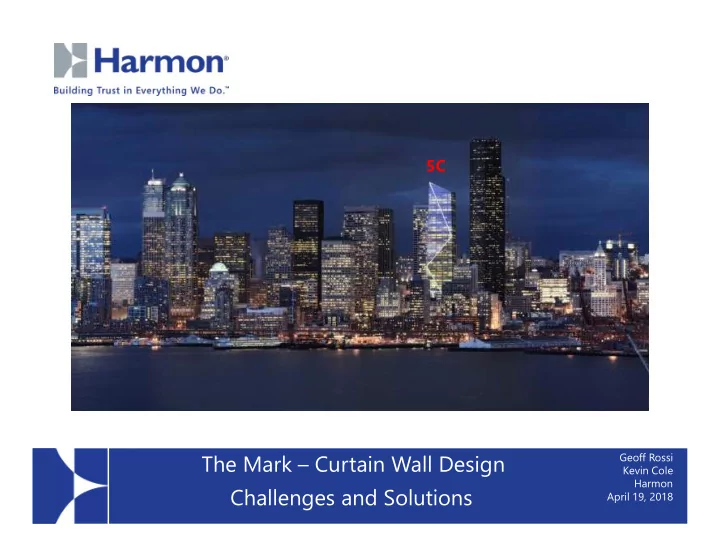
The Mark – Curtain Wall Design Challenges and Solutions
Geoff Rossi Kevin Cole Harmon April 19, 2018
PROJECT NAME Kevin Cole Harmon Challenges and Solutions Project - - PowerPoint PPT Presentation
5C The Mark Curtain Wall Design Geoff Rossi PROJECT NAME Kevin Cole Harmon Challenges and Solutions Project location April 19, 2018 Provider Number: 40107205 The Mark: Exterior Curtain Wall Challenges and Solutions 2018 04 19 Geoff,
5C
Geoff Rossi Kevin Cole Harmon April 19, 2018
Provider Number: 40107205
2018 04 19
April 4, 2018
Credit(s) earned on completion of this course will be reported to AIA CES for AIA members. Certificates
members and non-AIA members are available upon request. This course is registered with AIA CES for continuing professional
include content that may be deemed or construed to be an approval or endorsement by the AIA of any material of construction or any method or manner of handling, using, distributing, or dealing in any material or product.
___________________________________________ Questions related to specific materials, methods, and services will be addressed at the conclusion
Exterior Curtain Wall challenges and solutions for one of Seattle’s newest towers, The Mark will be discussed. The Presentation will provide information and learning as it relates to specific building design features
learn about the specific system features that were utilized to meet the thermal requirements of the project, and discuss installations sequencing, and weathering quality control challenges between the brace and the curtain wall.
runs the entire height of the project
sloping and variable horizontal angles to create different facets.
including high performance glass
consistent quality control.
At the end of the this course, participants will be able to:
6
7
8
Upper Side Stack Joint Lower Side Male/Female
9
10
11
Detail Angle Elev. Detail Angle
403
W1 401 +6.6893
404
W2 405 +3.9901
415
W3 417
419
W4 421
401 +6.3403 S1 402
405 +3.8141 S2 406 +0.4865
416
S3 415
419
S4 418
14 different angles, 3 sets of dies
12
Facets N1 and W1; Detail 401; Angle +6.3403 to +6.6893; Dies 834406, and 834110
13
Facets N3 and W2; Details 405, and 416; Angles +3.8141, and +3.9901; Dies 884407, and 834103
14
Facets E3, S1, S3; Details 402, and 415; Angle; 0.0000; Dies 834405, and 834100
15
Facets E1, E2, E4, N3, N4, W3, W4, S2, and S4; Details 403, 404, 406, 416 to 421; Angles +0.4865 to -2.3256; Dies 884405, and 834100
16
Facets Angle Dies
W2, S2 95.40 834008, 834009
S1, E1 88.60 834001, 834002
N2,E2 93.00 834006, 834007
W1, N1 90.50 834004, 834005
W4, S4 91.15 834004, 834005
S3, E3 90.50 834004, 834005
N4, E4 90.47 834004, 834005
W3, N3 94.33 834008, 834009
7 different angles, 4 sets of dies, Rule of thumb is 1.5 degrees
17
Column H-1; Facets W2, S2; Angle 95.40; Dies 834009, 834008
18
Column H-9; Facets S1, E1; Angle 88.60; Dies 834002, 834001
19
20
– Seattle Energy Code requires U = 0.32 for glazed areas. – Requires thermal simulations of standard size and a physical test of standard size sample to validate simulations to obtain NFRC Label Certificate.
– Seattle building department requires NFRC Label Certificate submittal prior to beginning installation.
21
22
23
24
25
26
27
55
expressed on skin
separate facets
56
57
58
59
60
61
62
63
64
65
66
67
68
69
70
71
72
73
74
75
76
77
78
79
80
81
A New Icon on the Seattle Skyline 5C
This concludes The American Institute of Architects Continuing Education Systems Course
Penny Short 206-538-2208 pshort@rdh.com