Progress in photo cathode laser pulse shaping towards ultimate - - PowerPoint PPT Presentation

progress in photo cathode laser pulse shaping towards
SMART_READER_LITE
LIVE PREVIEW

Progress in photo cathode laser pulse shaping towards ultimate - - PowerPoint PPT Presentation

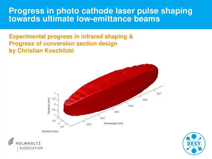
Progress in photo cathode laser pulse shaping towards ultimate low-emittance beams Experimental progress in infrared shaping & Progress of conversion section design by Christian Koschitzki Photo Injector Test facility at DESY in Zeuthen


slide-1
SLIDE 1

Experimental progress in infrared shaping & Progress of conversion section design by Christian Koschitzki

Progress in photo cathode laser pulse shaping towards ultimate low-emittance beams

slide-2
SLIDE 2

Christian Koschitzki | Progress on ELLA2 | 05.09.2018 | Page 2

Photo Injector Test facility at DESY in Zeuthen (PITZ)

x Fx px x x Fx px x

Pulse should only experience linear distortions

Homogeneous ellipsoidal electron bunch results in linear phase space  ultimate low emittance

laser

electron bunch

cathode acceleration

slide-3
SLIDE 3

Christian Koschitzki | Progress on ELLA2 | 05.09.2018 | Page 3

Laser Shaping at PITZ

> Proof of principle demonstrated with IAP system (single SLM -> dual path) at PITZ in 2016

x (mm) t (ps)

  • 10
  • 5

5 10

  • 20
  • 10

10 20

Comparison with simulated e- beam shapes (500pC):

Gaussian laser Flattop laser Ellipsoidal laser

similarity in shape

  • J. Good et al., Proc. 38th FEL Conf., WEP006 (2017)

Problems: pointing stability, spectral width and conversion

Measurement

@EMSY @PST.Sc1

> „Generation of flat-top picosecond pulses by coherent pulse stacking in a multicrystal birefringent filter“, Ingo Will & Guido Klemz

Optics Express, Vol. 16, Issue 19, pp. 14922-14937 (2008)

0.2 0.4 0.6 0.8 1 5 10 15 20 25 30 OSS Signal (a.u.) Time (ps) 0.2 0.4 0.6 0.8 1 5 10 15 20 25 30 35 OSS Signal (a.u.) Time (ps)

slide-4
SLIDE 4

Christian Koschitzki | Progress on ELLA2 | 05.09.2018 | Page 4

Example for the key principles: The spectrograph

4f (Image)

CCD

2f

CCD SLM Only rectangular shapes because of projection

Polarizing beamsplitter Waveplate

Reflect and reverse

  • ptical path

Repeat for 2nd spatial domain

slide-5
SLIDE 5

Christian Koschitzki | Progress on ELLA2 | 05.09.2018 | Page 5

Schematic setup of infrared shaping

SLM λ-X Shaper SLM λ-Y Shaper Pharos laser

Dove Prism Image Start Image Out

Cylindrical Lens Spherical Lens Grating SLM

  • mod. VBG

VBG

Volume Bragg Grating Shaper

Faraday rotator Polarizing BS

Waveplate

Standard VBG Modified VBG Output Power: 20W

  • Rep. Rate: 0.1-1 MHz

Pulse duration: 0.25 – 15 ps Wavelength: 1030 nm Provides rotational symmetry

slide-6
SLIDE 6

Christian Koschitzki | Progress on ELLA2 | 05.09.2018 | Page 6

Shaping with spectrograph feedback

λ-X Shaper Spectrograph

Spectrograph Inverted MZ Interferometer Pharos laser SLM SLM

Gaussian (unshaped) profile

slide-7
SLIDE 7

Christian Koschitzki | Progress on ELLA2 | 05.09.2018 | Page 7

3D Measurement with Spectrograph Slit Scan

Spectrograph Data  Slices in λ-X along Y Transverse Slices

λ x y

slide-8
SLIDE 8

Christian Koschitzki | Progress on ELLA2 | 05.09.2018 | Page 8

Nonlinear Conversion

Input beam Wavelength: 1030 nm Fourier Limit: 0.211 ps Diameter: 0.25 mm Pulse duration: 30 ps Pulse Energy: 20 µJ Material: BBO Propagation: 2.5 mm BBO Walk Off: 57 mrad

 Without angular chirp Efficiency 20%

Matched angular chirp: AC = 0.275 mrad per nm Slant angle = 25 deg

chi23d.com Harmonic Pulse (VIS) Pump Pulse (IR) Animation over 2.5 mm propagation  With angular chirp Efficiency 36%

slide-9
SLIDE 9

Christian Koschitzki | Progress on ELLA2 | 05.09.2018 | Page 9

57 mrad * 2.5 mm= 143 micron Input beam Wavelength: 1030 nm Fourier Limit: 0.211 ps Diameter: 0.25 mm Pulse duration: 30 ps Pulse Energy: 20 µJ Material: BBO Propagation: 2.5 mm BBO Walk Off: 57 mrad

 Without angular chirp Efficiency 20% chi23d.com Harmonic Pulse (VIS) Pump Pulse (IR) Animation over 2.5 mm propagation  With angular chirp Efficiency 36%

Matched angular chirp: AC = 0.275 mrad per nm Slant angle = 25 deg

Nonlinear Conversion

slide-10
SLIDE 10

Christian Koschitzki | Progress on ELLA2 | 05.09.2018 | Page 10

Conversion to Fourth Harmonic

Softening in 0.8 mm BBO

f1

𝜄𝑗𝑜

f1+f2

BBO

f2

LBO Nonlinearity: Eout ~ Ein

4

20 µJ in  2.75 µJ out (14%) 10 µJ in  0.38 µJ out (4%) Broadband Phasematching: Suppression of spectral components due to wavelength dependent phase matching  Compensate with matched angular chirp Spatial Walk Off: Edge Softening due to propagation difference between pump and harmonic beam.

slide-11
SLIDE 11

Christian Koschitzki | Progress on ELLA2 | 05.09.2018 | Page 11

First Conversion Tests and Outlook

f300 f-250 f200 f500 f80 f250 f150 LBO 4mm Image Plane CCD

Variable Magnification Telescope Image in IR (1030 nm) Image after first Conversion in VIS (515 nm) Image in IR from old IAP system Collaboration with Chiang Mai University Thailand by Narupon Chattrapiban

slide-12
SLIDE 12

Christian Koschitzki | Progress on ELLA2 | 05.09.2018 | Page 12

Summary & Outlook

> 3D shaping capabilities in IR demonstrated > Image preservation in Second Harmonic shown > Preparing for Fourth Harmonic (UV) experiments (UV Spectrograph) > Investigation of time coordinate using cross correlation > Improved 3D shaping with Volume Bragg Gratings

Thank you for your attention